
Farewell to Unexpected Power Outages|3MW+10MWh PV-ESS Microgrid, Building a Reliable Continuous Power Supply Foundation for the Plant
1. Project Overview
This project is located in an industrial zone in north-central Mexico, serving a large local agricultural product deep-processing and cold chain storage & transportation plant. The plant originally relied on the utility grid backed by diesel generator sets for power supply. The regional power grid suffers from weak stability, with frequent voltage fluctuations and unexpected blackouts. Cold chain units and production processing equipment are sensitive loads. Short power interruptions and voltage distortion will lead to loss of production materials and production line shutdowns, posing major risks to the continuous operation of the plant.
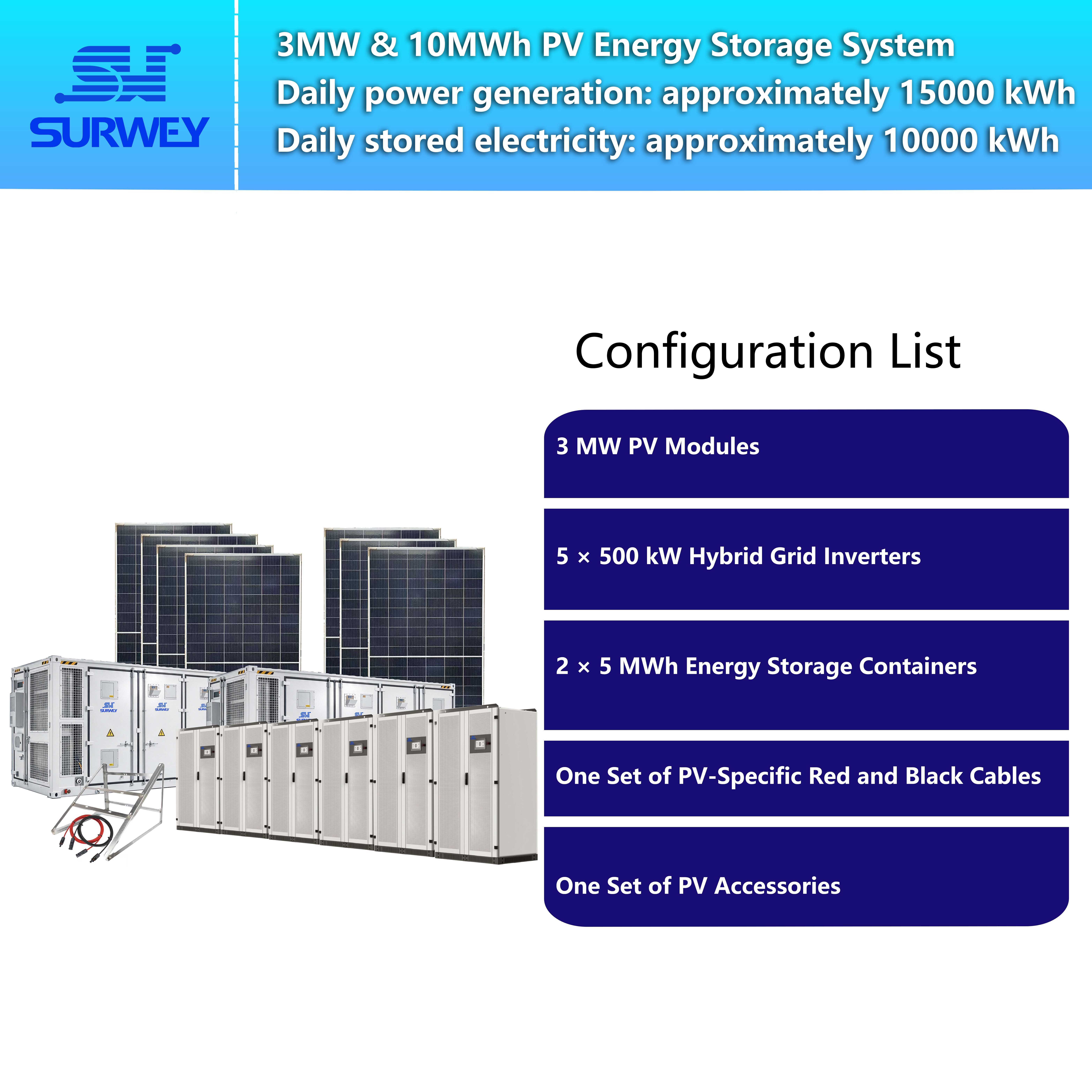
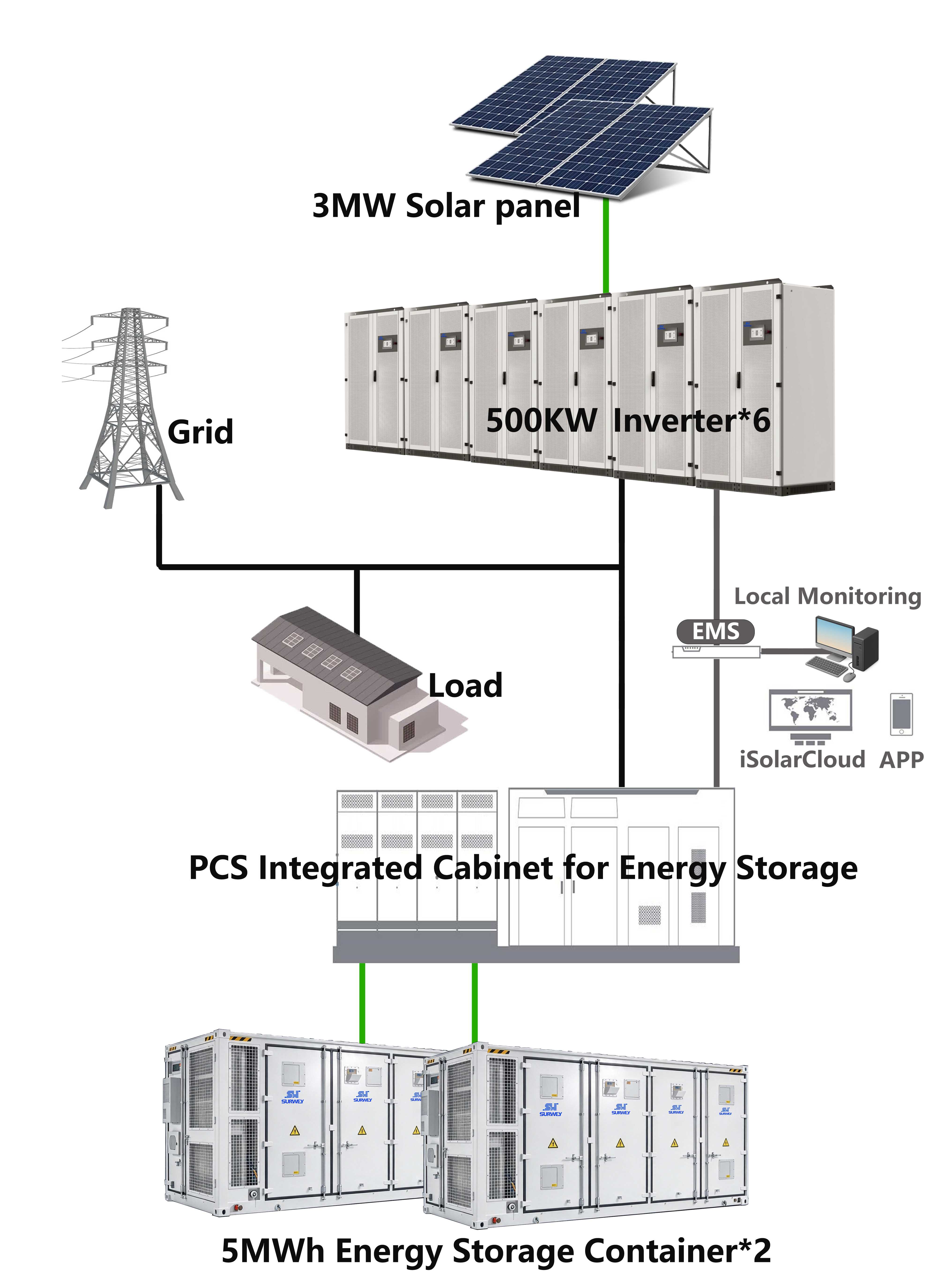
To address the weakness in power supply reliability and build a self-controlled on-site energy supply system, this project adopts an integrated PV + Energy Storage + Hybrid Inverter microgrid solution. It creates a PV-ESS microgrid system with seamless switching between grid-tied and off-grid modes. The complete system consists of N-type monocrystalline high-power PV modules, liquid-cooled containerized energy storage cabins, integrated hybrid inverters, centralized converter & step-up integrated cabins, coordinated by EMS (Energy Management System) and BMS (Battery Management System).
The installed DC capacity of the PV array is approximately 3 MW, with an energy storage capacity of 10.03 MWh. Six sets of 500 kW integrated hybrid inverters are deployed to realize self-consumption, peak shaving and valley filling, off-grid power backup during grid faults, while increasing the proportion of green power consumed on-site to meet the requirements of green production and operation.

PV Module Installation Drawing
2. Core Equipment Parameters & Product Introduction
2.1 Integrated Hybrid Inverter (Core of Microgrid Control)

500 kW Integrated Hybrid Inverter
Six units of 500 kW integrated hybrid inverters are selected as the core control units for this project. This model is specially developed for commercial and industrial PV-ESS microgrid scenarios. It integrates MPPT PV tracking modules, step-up transformers, STS static transfer switches and maintenance bypass functions. It supports multi-unit parallel operation and linkage with the EMS platform, and is compatible with three-phase unbalanced load output, acting as the dispatch hub of the entire microgrid system.
Grid-tied Mode Rated output power: 500 kW; Maximum output power: 550 kW Rated output voltage: 400 V; Operating voltage range: 320~460 V, complying with local low-voltage distribution standards Power factor: Adjustable from 0.9 leading to 0.9 lagging Grid-tied current total harmonic distortion THDi<3%, reducing harmonic pollution to the public utility grid.
Off-grid Mode Capable of establishing a stable AC voltage source independently. Rated output power: 500 kW Voltage total harmonic distortion THDu≤1% for linear loads, ≤5% for non-linear loads Overload tolerance: Continuous operation at 110% rated load; 120% overload sustainable for 1 minute to withstand the inrush current of motor-type loads at startup.
PV Access Performance Single inverter supports maximum PV input power of 720 kW, equipped with multiple independent MPPT channels. MPPT voltage tracking range: 250 V~850 V, adapting to voltage variations of high-power modules under high and low temperature conditions. PV strings with different quantities can be allocated to separate MPPT channels to mitigate generation losses caused by string mismatch.
Battery Access Performance Battery voltage adaptation range: 500~850 V, supporting high-power bidirectional charging and discharging. It can be directly connected to the DC side of energy storage cabins to store surplus PV power and discharge batteries during peak load periods.
Hardware & Communication Air-cooled heat dissipation, IP20 protection rating. Stable operation from -30℃ to +55℃, available up to 5000 m altitude (derating operation above 3000 m). Equipped with a local LCD touch screen. Communication protocols: RS485, CAN, TCP/IP. It connects to BMS and EMS platforms for remote monitoring and strategy deployment. The multi-parallel technology enables coordinated operation of six inverters with mutual redundancy. When one unit is under maintenance, the remaining units maintain the power supply capacity of the system.
2.2 650W N-type Monocrystalline PV Module (Energy Harvesting Unit)
The PV array of this project adopts 650W N-type monocrystalline bifacial modules, with a total quantity of 4616 pieces, serving as the primary energy input of the system. Adopting a 132 half-cut cell design, the N-type module features excellent low-light power generation performance and low temperature attenuation, suitable for the high-temperature and high-irradiance outdoor environment in Mexico.
Under STC conditions: Power 650 W, module efficiency 24.4%; Open-circuit voltage 49.7 V, operating voltage 41.5 V; Maximum power temperature coefficient -0.29%/℃, which means lower power degradation under intense sunlight. Maximum system DC voltage tolerance up to 1500 V, meeting the requirements of high-voltage string design. Both front and rear sides use tempered coated glass. The junction box reaches IP68 protection rating. Mechanical load capacity: 5400 Pa front side and 2400 Pa rear side for wind and snow loads, ensuring long-term outdoor reliability.
2.3 Liquid-cooled Containerized C&I Energy Storage Cabin (Energy Storage Unit)
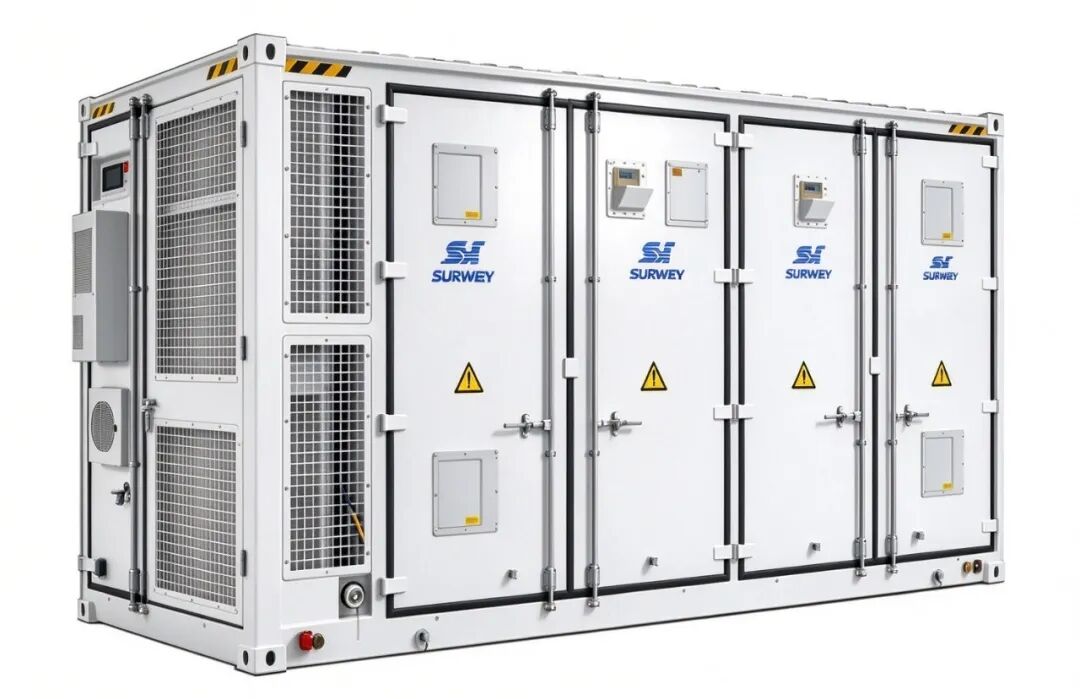
5.015 MWh Liquid-Cooled Containerized C&I Energy Storage
Two liquid-cooled energy storage containers are deployed, with a rated capacity of 5.015 MWh per cabin and a total capacity of 10.03 MWh. The cells adopt lithium iron phosphate chemistry, configured as 12 cells in series and 1 parallel, with 416 PACK assemblies. The system DC voltage range is 1331 V~1497 V.
The energy storage cabin supports 0.5C constant current charge and discharge. DC charge-discharge efficiency reaches 95% under rated conditions. The cycle life of the system is up to 10,000 cycles, with a designed calendar life of 20 years, matching long-term charge-discharge cycles for commercial and industrial applications. Liquid cooling is adopted for precise temperature equalization control, limiting the temperature difference between internal cells within 3℃. It maintains cell consistency and slows down capacity degradation under the high-temperature summer climate in Mexico. For safety, PACK-level perfluorohexanone fire suppression devices are equipped, with optional aerosol and water-based fire protection extensions. The whole cabin has an IP54 protection rating and operates within -40℃~+55℃. Communication interfaces include CAN, RS485 and Ethernet, supporting Modbus protocol. It uploads real-time data such as cell voltage, temperature, SOC and fault alarms to the EMS system, and coordinates charge-discharge strategies with inverters.
2.4 Centralized Converter & Step-up Integrated Cabin
The converter & step-up integrated cabin undertakes AC collection, voltage step-up and power distribution protection for the system. It converges the AC output from six hybrid inverters and raises the voltage level to connect with the plant power distribution system. Metering, relay protection and data acquisition modules are integrated inside the cabin. It integrates power distribution monitoring, protection and data collection functions, reducing scattered cabinet arrangements on site, simplifying field wiring and lowering later maintenance workload. It links with the EMS system to monitor grid-tied status and isolate faults.
3. PV Array String Design
A total of 4616 pieces of 650W PV modules are used. The string design follows the core principle that the number of modules connected in series on the same MPPT branch shall be consistent to avoid generation mismatch losses caused by parallel branches with different voltages. Details are as follows:
Standard branch configuration: 16 modules connected in series per PV string, 288 strings in total, consuming 4608 modules. The 288 strings are evenly distributed to six 500 kW hybrid inverters, with 48 standard branches connected to each inverter. Calculation of operating voltage per string: 16 modules in series deliver approximately 664 V under standard conditions, falling within the optimal MPPT tracking range of 250~850 V of the inverter. The calculated open-circuit voltage under low temperature is lower than the maximum DC withstand voltage threshold of the inverter, with sufficient safety margin to prevent shutdown triggered by overvoltage protection at low temperatures. The total input power of 48 strings per inverter matches the 500 kW rated output capacity for reasonable capacity matching.
Handling of remaining modules: The remaining 8 modules form one separate string, assigned to an idle independent MPPT channel of one inverter. This branch operates independently without paralleling with the standard 16-module strings. This arrangement avoids module waste while ensuring consistent string quantity within the same MPPT channel to maximize overall generation efficiency.
The total DC installed capacity of the PV array is approximately 3 MW. Benefiting from the superior low-light and high-temperature performance of N-type modules, it continuously supplies power to plant loads during daytime under local solar resource conditions, and surplus power is stored in the energy storage cabins.
4. System Operation Logic
System Operating Principle Video
The complete PV-ESS microgrid has two operating modes: grid-tied and off-grid microgrid mode, automatically switched and dispatched by hybrid inverters and the EMS.
Grid-tied Mode (Utility Grid Normal) PV power supplies the plant production and cold chain loads with priority. When PV output exceeds real-time load demand, excess DC power charges the energy storage cabins via inverters. When solar irradiance is insufficient and PV output is lower than load demand, energy storage cabins discharge or the utility grid supplements power supply. Based on load profiles and solar forecast, the EMS autonomously schedules charging and discharging periods of energy storage for peak shaving to maximize on-site consumption of PV power.
Off-grid Mode (Utility Grid Fault / Blackout) The STS static transfer switch rapidly disconnects from the utility grid. Hybrid inverters switch to voltage source mode and establish a stable 400 V AC microgrid bus relying on energy storage cabins. PV power participates in power supply simultaneously to sustain critical sensitive loads such as cold chain equipment and production lines without interruption. After the utility grid recovers, the system automatically detects grid parameters, synchronizes smoothly and switches back to grid-tied mode. The whole process requires no manual operation and no transition support from diesel generators.
Multi-unit Coordination Logic Six hybrid inverters run in parallel and are dispatched uniformly by the EMS to share load power evenly. When one unit is under maintenance, the remaining units automatically share the load to guarantee power continuity of the microgrid with fault tolerance and redundancy.
5. Project Value
✅ Improved Power Supply Reliability: Solves blackouts and voltage disturbances caused by unstable local utility grids. It builds a power backup system for sensitive cold chain and processing loads to avoid production losses from unexpected outages, serving as the power foundation for stable plant operation. ✅ Local Utilization of Clean Energy: PV power is generated and consumed on-site, raising the share of green power in the plant and reducing dependence on fossil-fueled utility power, meeting the ESG and low-carbon evaluation requirements of supply chains. ✅ High Operational Flexibility: The microgrid system supports later capacity expansion of inverters and energy storage equipment to accommodate future load growth of the plant. Operating strategies can be remotely adjusted via EMS to adapt to power consumption changes across seasons and production schedules. ✅ Maintenance-friendly: Core equipment adopts cabinet-type and containerized prefabricated design, with most commissioning completed in factory. It shortens on-site construction cycles. Built-in status monitoring and fault alarm functions allow maintenance staff to check operating data and locate faults quickly via local touch screens or remote platforms.
6. Project Summary
This project takes integrated hybrid inverters as the microgrid control core, paired with high-power N-type PV modules and liquid-cooled lithium iron phosphate energy storage cabins to build a 3MW/10MWh PV-ESS integrated microgrid. The design adapts to the grid conditions in Mexico and the load characteristics of cold chain production plants. The PV string scheme undergoes voltage verification to balance power generation efficiency and equipment safety. Equipment selection fully considers the local high-temperature and high-irradiance climate.
The whole system supports both grid-tied self-consumption and independent off-grid backup, putting energy control in the hands of the plant. This solution not only resolves current power supply pain points, but also reserves expansion space for subsequent energy upgrading and continuous green power growth of the plant. It is a mature PV-ESS microgrid solution suitable for commercial and industrial plants in Latin American regions with weak power grids.


