
Escaping Recurring Power Outages: A Field-Proven Residential Solar-Storage Solution in Zimbabwe
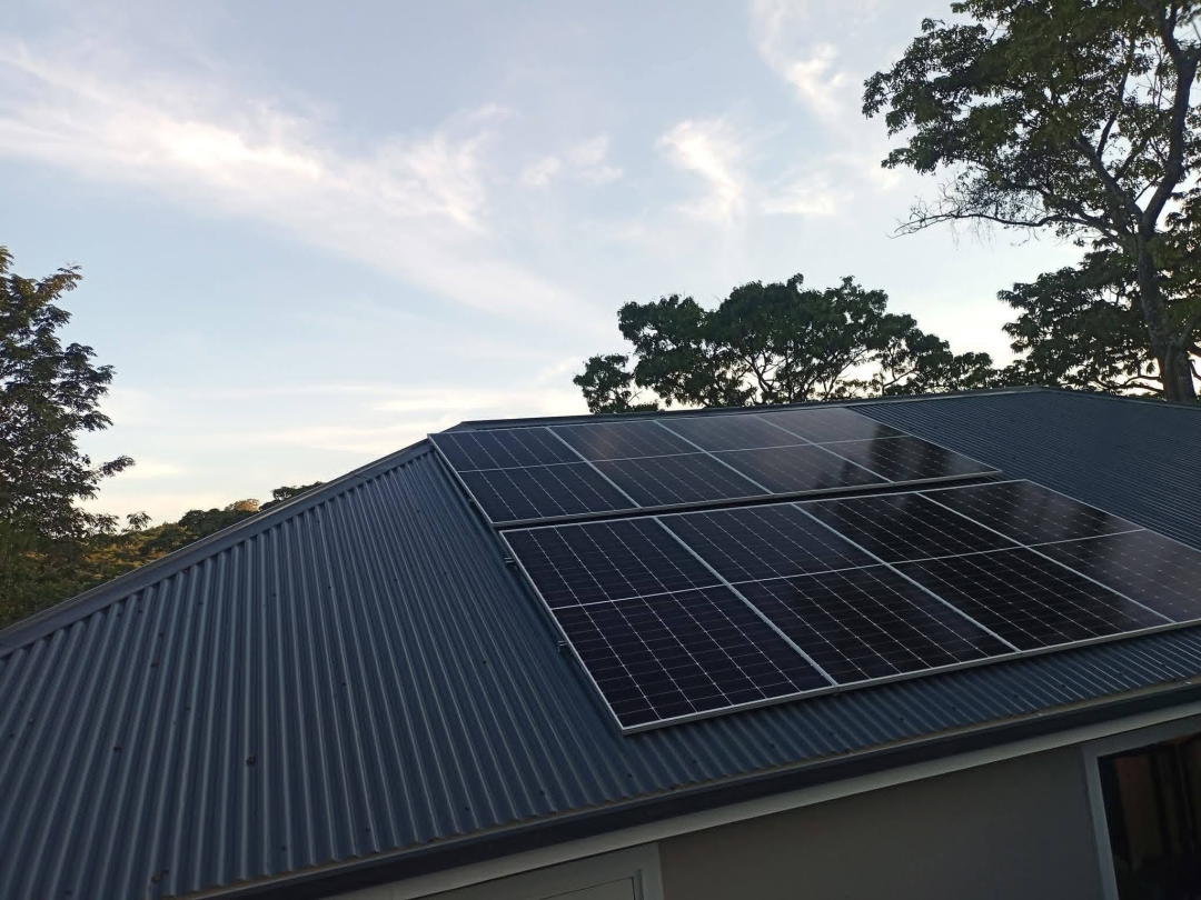
(Picture of solar panel installation)
1. Project Background
Located in a residential suburb north of Harare, this system serves a local logistics operator and his family of five living in a standalone courtyard. Chronic scheduled power cuts are a long-standing nuisance for local residents, with daily outages commonly lasting over six hours. The duration extends further during the rainy season when overhead line failures become frequent.
The homeowner’s power requirements are practical and clear: freezers and refrigerators must remain energized at all times; night lighting, fans and networking equipment need stable supply; and the deep-well pump should operate reliably during daytime for water pumping. The existing service entry is single-phase 230 V, with no planned modifications to the original distribution wiring. The client sought one integrated system to resolve these daily power pain points.
We monitored the site load continuously over three days. The household consumes 9–11 kWh daily. Baseline night load stays between 300 W and 500 W, while the peak daytime draw comes from the deep-well pump with high inrush current, bringing the overall combined load peak to approximately 4.2 kW. This load profile matches a 6 kW hybrid solar-storage system perfectly.
2. Site Conditions and Design Constraints
Harare sits at nearly 1,480 m above sea level in the Southern Hemisphere with favourable annual irradiance, though marked seasonal variation exists. Irradiation is abundant in the dry season, while prolonged overcast spells are common in the rainy season. Large diurnal temperature swings push module backsheet temperatures high at midday; conversely, low ambient temperatures raise the PV open-circuit voltage. Both factors received priority consideration in the design.
The roof features colour-coated steel sheeting, facing due south — the optimal orientation for solar capture in the Southern Hemisphere — at a tilt angle of 15°, with ample available mounting space. Based on module dimensions, the final array layout comprises two rows of six panels each, totalling twelve modules, neatly arranged with sufficient clearance to avoid mutual shading.
Local grid voltage fluctuates widely, and lightning-prone rainy seasons bring voltage spikes. Therefore, the hybrid inverter was specified with a wide AC input window, supplemented by surge protection to mitigate equipment risks induced by grid instability.
3. Core Equipment
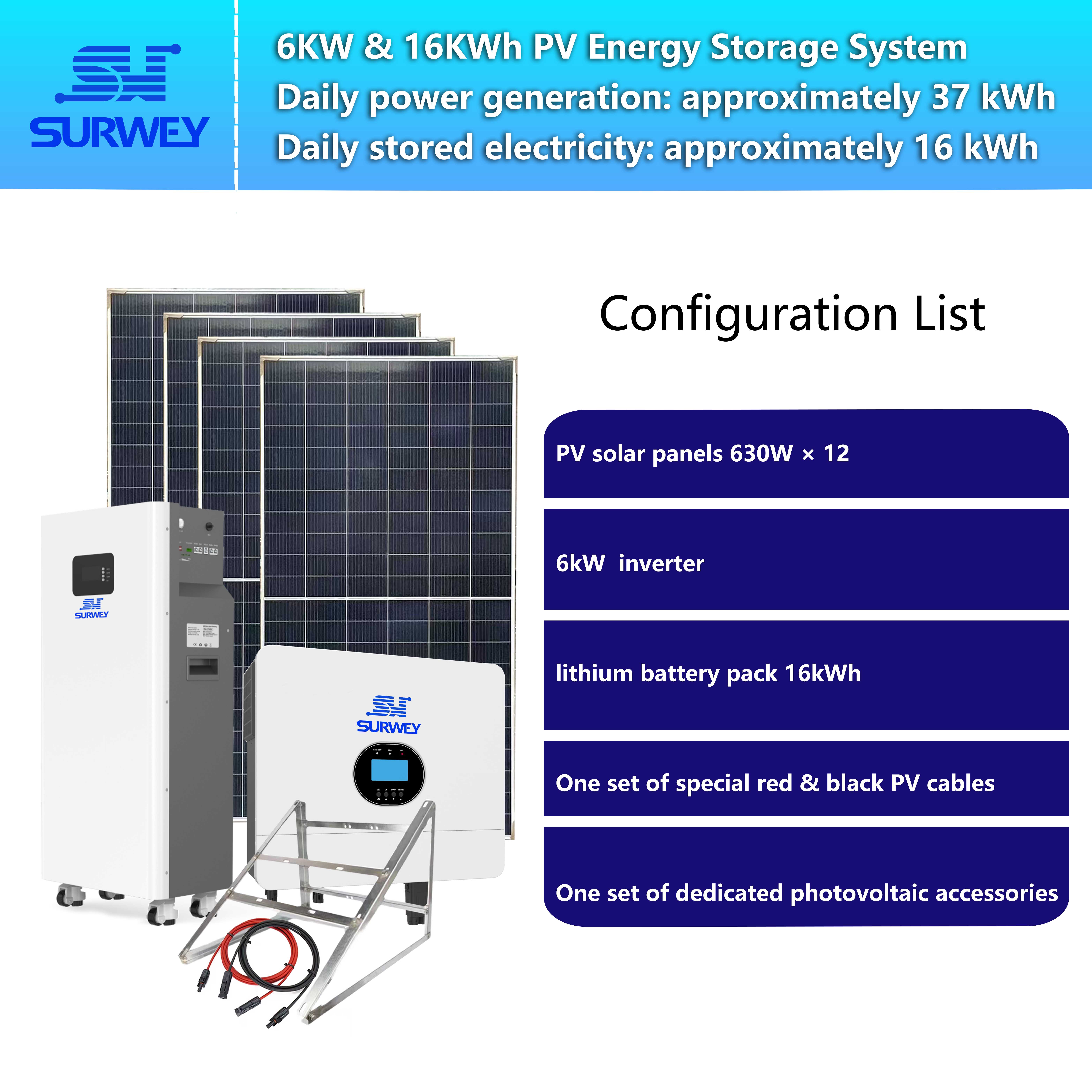
The complete setup consists of a hybrid inverter, floor-standing energy storage battery and bifacial PV modules.
Hybrid Inverter
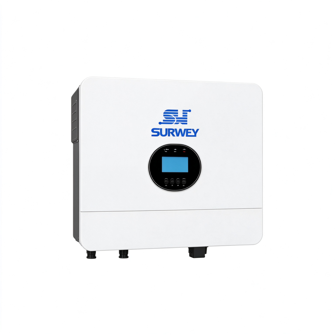
Rated power: 6,000 W, capable of a short-duration peak output of 12,000 W. It delivers pure sine-wave output for single-phase 230 V mains and automatically switches between 50 Hz and 60 Hz. It incorporates two independent MPPT solar trackers with a maximum PV input power of 8,000 W. The MPPT operating voltage window spans 120–450 Vdc, with a maximum allowable PV open-circuit voltage of 500 Vdc. The maximum PV charging current is 100 A and the maximum mains charging current is 80 A. Up to six units can be paralleled, though a single unit satisfies this household’s demand. Transition between grid and battery supply is rapid, so connected loads barely detect any interruption.
Floor-Standing Energy Storage Battery
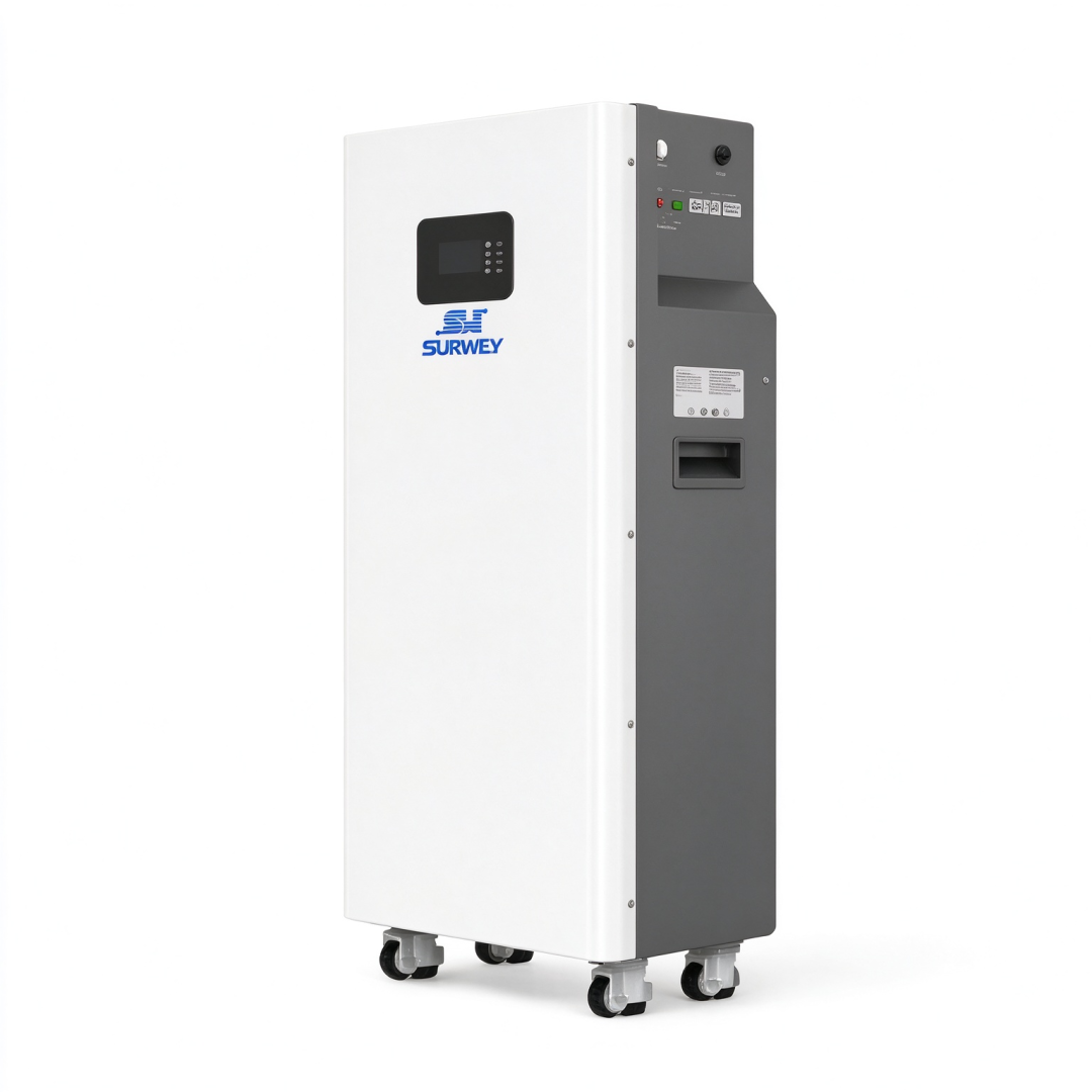
16 kWh floor-mounted lithium iron phosphate battery
Nominal voltage: 51.2 V, usable capacity 16 kWh. This wheeled battery unit is placed indoors. It supports multiple communication protocols, and its built-in display shows real-time state of charge (SOC), temperature and alarm codes. The maximum charge and discharge current reaches 200 A, with a usable depth of discharge up to 90%. Multiple units may be paralleled for capacity expansion, and it offers stable cycling performance. Integrated thermal management automatically derates output under high temperatures.
Bifacial PV Modules
630 W n-type monocrystalline bifacial modules. Their open-circuit voltage, operating voltage and current parameters align well with the inverter’s MPPT window. Each module is fitted with bypass diodes, and the junction box carries an IP68 ingress rating to deliver reliable rear-side power gain. The module voltage temperature coefficient forms the foundation for our string voltage verification.
4. String Design (12 Modules, Equal Count per String)
The homeowner specified an equal number of panels in both PV strings to simplify maintenance and fault diagnosis. We eliminated several candidate layouts through validation:
- Twelve modules in one single series string: the open-circuit voltage under low temperature exceeds the inverter’s 500 V limit and is unworkable.
- Uneven configurations such as 5+7 or 4+8: the two MPPT channels would operate at mismatched voltages, causing operating-point interference, untidy roof layout and complications for future expansion.
- Direct parallel connection of identical strings: the single-channel current limit of the MPPT would be exceeded.
The final arrangement: six modules per string, two strings in total (6+6), connected separately to the two independent MPPT channels. Verification confirms adequate margin for the low-temperature open-circuit voltage to prevent overvoltage tripping. At hot midday, the module operating voltage remains above the minimum MPPT activation threshold, and the operating current of each string stays within the single-channel current limit of the inverter. Total installed PV power reaches 7,560 W, below the inverter’s maximum PV input rating. Minor power limiting occurs on bright sunny days, which is normal operational behaviour.
(Video demonstrating system operating principles)
5. Inverter and Battery Matching Logic
The inverter’s DC bus voltage matches the battery’s nominal voltage. CAN communication enables the inverter to read real-time BMS data. Charge and discharge protection is governed primarily by the battery BMS for enhanced safety. The maximum solar charging power translates to a moderate charging rate for the battery. During prolonged overcast periods, mains backup charging quickly restores battery capacity to usable levels. The DC current drawn from the battery under full system load remains within the battery’s continuous rating, and short transient inrush loads fall within its permissible peak current.
For parameter configuration, the discharge cut-off SOC is set at 20% as an emergency reserve. The daily charging upper limit is 95%, and an automatic full charge runs once weekly to calibrate the SOC reading and mitigate state drift common with lithium iron phosphate cells.
6. System Operation Logic
Solar power prioritises household loads during daylight hours. High-consumption tasks such as water pumping and laundry are recommended during peak irradiance. Excess solar energy charges the battery; once fully charged, the PV output throttles automatically. This system is configured not to export surplus power back to the utility grid.
As sunlight fades in the evening, the battery takes over supply. Nighttime base consumption is modest, and a full battery from a sunny day generally sustains overnight critical loads. When grid supply fails, the inverter switches instantly to battery mode, keeping routers and freezers running without rebooting. Special care applies to inductive loads like the water pump owing to its large starting inrush current; operators should avoid running it simultaneously with other heavy loads.
Estimated against local irradiance datasets, the system yields substantial annual generation, nearly all of which is consumed on-site with a high self-consumption ratio. Energy production is robust in the dry season, while mains charging provides reliable backup through extended rainy-season overcast spells.
7. Installation: Subtle yet Critical Construction Practices
Colour-coated steel roof clamps and mounting rails are adopted for the racking, avoiding penetrations through the roof membrane, with sealing completed at all fixing points. A 0.9 m gap separates the front and rear rows of modules to avoid shading around the winter solstice. The two PV strings are laid with matched cable lengths to minimise voltage imbalance between channels. 4 mm² specialised PV DC cable is deployed, and DC-side surge protection is fitted. A dedicated earthing run is installed, isolated from the building’s existing lightning protection conductor.
The battery unit sits in a ventilated indoor location away from direct sunlight. High indoor temperatures in the local summer trigger battery derating, so poor placement noticeably slows charging. With an IP20 rating, the inverter must be mounted indoors, with clearance around it and the battery for heat dissipation; no clutter should be stacked around the equipment.
8. Commissioning: Lessons from Three Months of Field Operation
The system has run reliably for three months, during which three typical on-site issues emerged:
- Pump start-up triggered overload alarms. This was resolved by adding a soft starter and advising the homeowner to stagger activation of heavy loads.
- During multi-day rainy overcast weather, the battery SOC dropped toward the protection threshold; the system smoothly switched to mains charging to restore usable capacity.
- Dust accumulates rapidly in the dry season. Without cleaning for two months, generation falls by 5%–8%. We advised the homeowner to rinse the modules monthly in the early morning, avoiding hot midday hours to prevent thermal shock to the panels.
The homeowner reported tangible relief: no more blackouts, and goods stored in the freezer are safe from spoilage. He enquired about future PV expansion. We confirmed that expansion is feasible, though new panels cannot simply be added into the existing strings; any extension must follow the six-module-per-string standard. This is a key benefit of adopting equal-length strings from the outset, establishing a consistent baseline for later upgrades.
9. Solution Summary
This 6 kW single-phase solar-storage design suits households around Harare facing frequent blackouts, single-phase grid entry and roughly 10 kWh of daily consumption. The 6+6 equal-string layout is a conservative, robust choice for this dual-MPPT inverter, delivering independent power tracking, eliminating inter-string mismatch and simplifying long-term maintenance. A system that serves reliably for decades depends less on headline equipment specifications and more on rigorous verification of low-temperature open-circuit voltage, high-temperature operating voltage and string consistency, paired with compliant installation and scheduled upkeep.


