
Venezuela Commercial & Industrial Rooftop PV-ESS Integrated Solution
Introduction
Power supply conditions in Venezuela are complex, with volatile grid stability and persistently high industrial electricity tariffs. Power outages and load shedding are regular challenges for many manufacturing facilities. For production-oriented enterprises, electricity bills represent substantial fixed costs. Grid disruptions lead to production line shutdowns and semi-finished product scrap, whose indirect economic losses often far exceed the cost of electricity itself.
A large number of local steel-structured factories feature well-suited rooftop space. Deploying photovoltaic and energy storage systems on idle factory rooftops for self-consumption, surplus power storage and emergency backup power during outages has become a practical solution for local industrial users to mitigate operational risks and control electricity expenses. This project targets a local processing plant with an available rooftop area of 800–850 m² and three-phase NEMA-standard industrial loads. Actual meter readings show the plant consumes 40,000 kWh monthly, averaging 1,333 kWh per day. In terms of load profile, daytime production accounts for 85% of total power consumption, while nighttime use makes up 15%. During peak production seasons for rush orders, the maximum daily electricity demand can reach 2,000 kWh. The rooftop has no high-rise obstructions and enjoys favorable solar irradiance, making it highly suitable for a PV-storage integrated system.
The complete solution fully complies with American NEMA frequency electrical standards. Equipment selection, string layout, energy storage capacity sizing and distribution supporting design are developed based on on-site rooftop conditions and real load curves. Full consideration is given to local construction practices and long-term operation & maintenance environments, with safety margins and provisions for future expansion reserved, forming a commercial and industrial PV-storage solution tailored to Venezuelan operating conditions. Core electrical configurations are refined and calculated strictly in accordance with inverter datasheets and measured PV module parameters to eliminate deviations from theoretical design and guarantee long-term stable system operation.
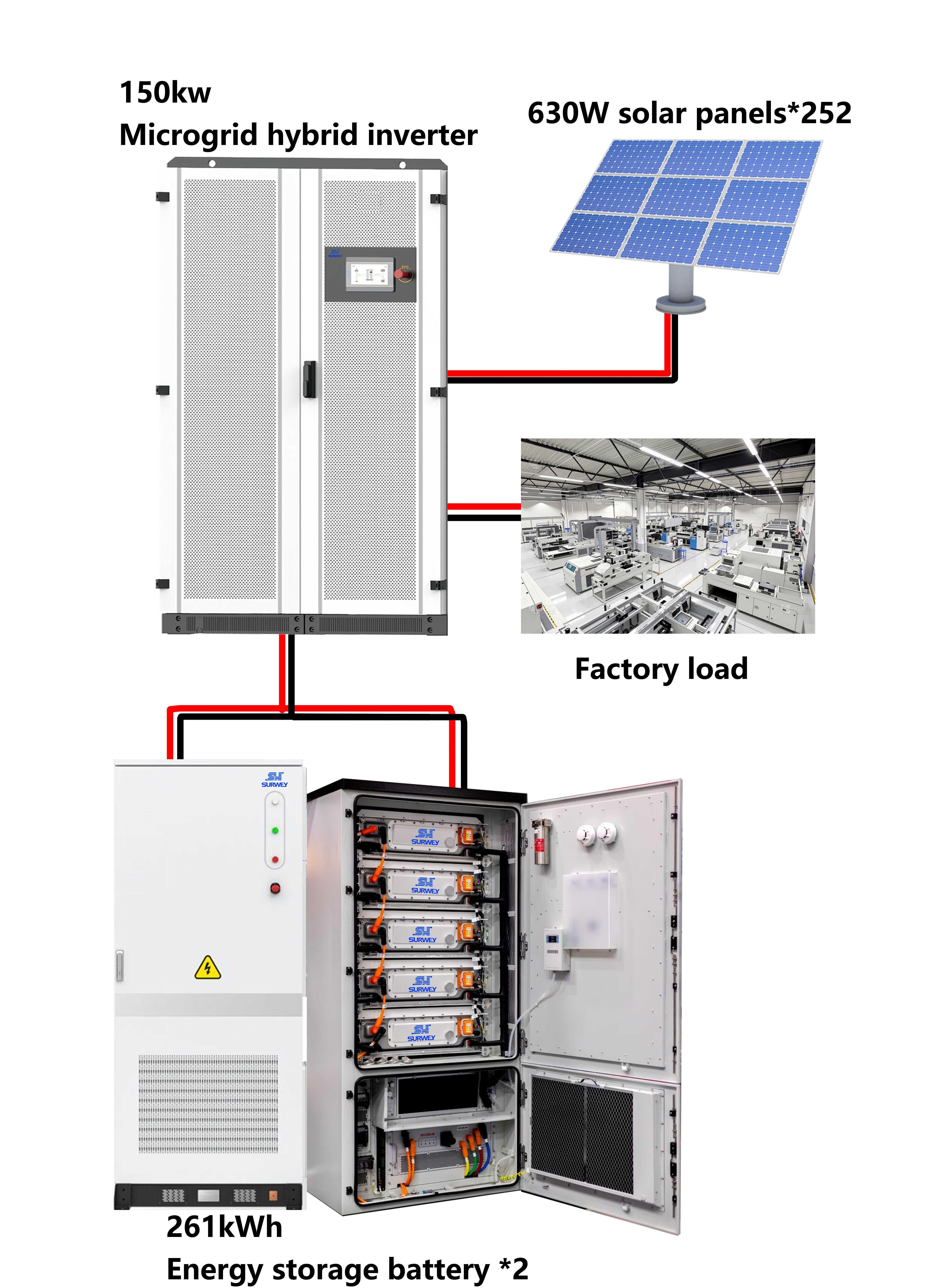
Topology Diagram of 150 kW / 522 kWh NEMA-Standard PV-ESS System
I. On-Site Operating Conditions & Design Premises
The factory building adopts a steel structure with color-coated steel tile roofing. The usable rooftop area ranges from 800 to 850 m². The roof surface is flat with no shading from large ventilation equipment or structures, allowing the PV array to be laid flat without elevated racking, which effectively cuts racking material and installation costs. The power supply follows the American three-phase NEMA frequency standard. All power conversion devices in the system adopt NEMA frequency architecture compatible with local industrial distribution standards, avoiding poor adaptability of high-frequency inverters to the volatile local grid.
The plant’s electricity consumption profile is highly representative and divided into three typical operating scenarios. All system configurations are precisely matched against real consumption data to prevent over-sizing or under-sizing.
Under regular production conditions, monthly power consumption is 40,000 kWh, equivalent to 1,333 kWh daily. Most electricity is consumed during daytime production hours, coinciding closely with peak PV generation. Power produced by solar modules is supplied directly to on-site equipment for on-site self-consumption, reducing grid electricity purchase and minimizing expensive peak-time power charges.
Nighttime loads account for 15% of daily consumption, mainly including equipment standby power, site lighting, security monitoring and other base loads. No PV generation is available at night. Without energy storage, this portion of power must be fully drawn from the utility grid. In the event of grid outages, critical nighttime support systems will also lose power, indirectly impairing equipment maintenance and site security management.
Peak production seasons represent high-impact load scenarios. During concentrated order periods, daily power demand can peak at 2,000 kWh with short-duration load surges. PV arrays alone cannot fully cover such demand, requiring coordinated discharge from PV and energy storage, with any remaining shortfall supplemented by the grid. This project is designed based on an average local peak sun hour of 5 hours, targeting a daily generation output of 800 kWh with a total energy storage capacity of 522 kWh. The system operates in grid-tied hybrid mode: PV power supplies site loads with priority; excess PV power is stored in batteries; when PV output is insufficient, energy storage discharges to fill the gap; if both PV and storage cannot satisfy loads, the system automatically switches to grid supply. In case of grid faults, off-grid mode activates to guarantee uninterrupted power for critical production loads, comprehensively accommodating all operating conditions of the factory.
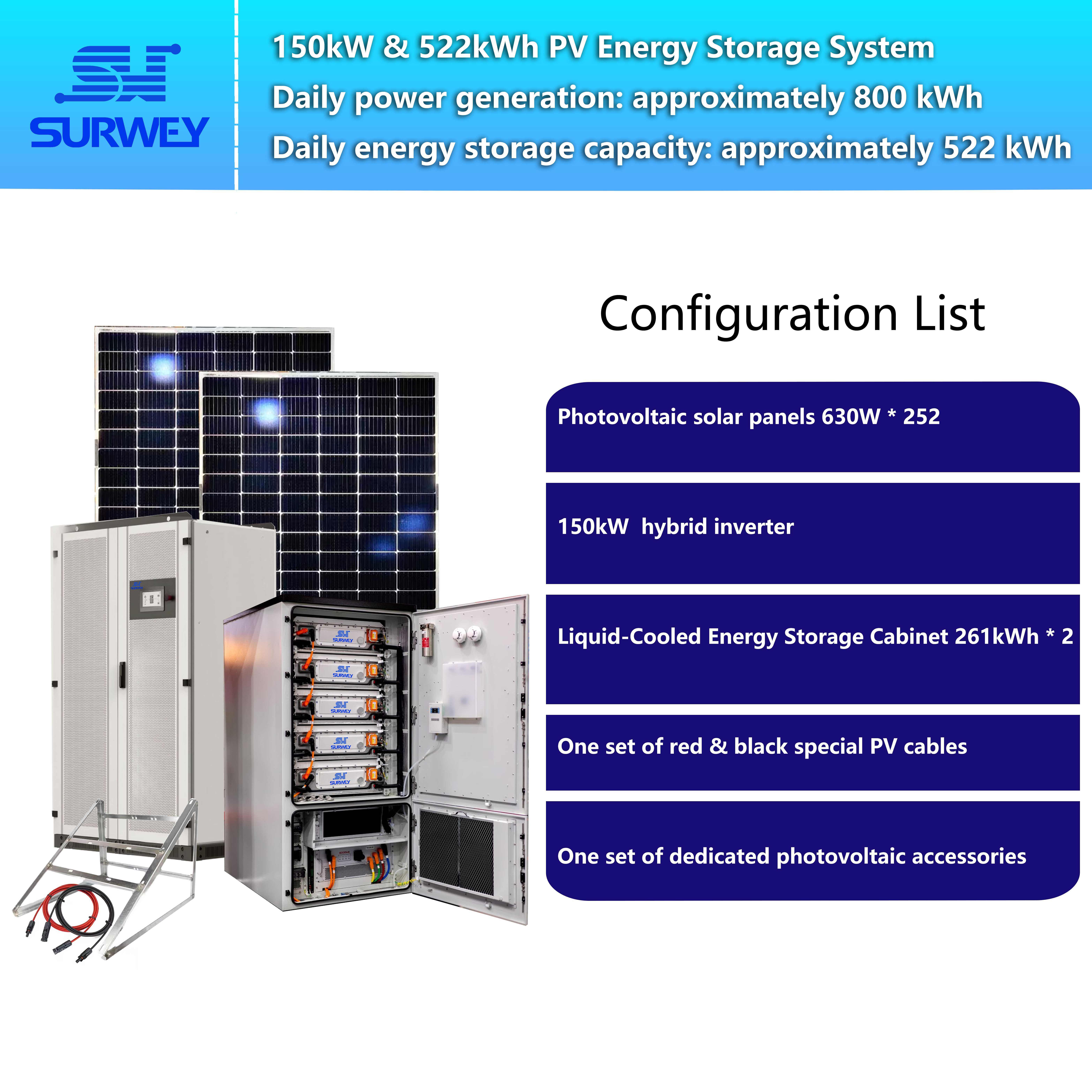
Configuration Diagram of 150 kW / 522 kWh NEMA-Standard PV-ESS System
II. PV Array Configuration & String Electrical Design (Including Refined Electrical Calculations)
The PV array serves as the energy source of the entire system. Large diurnal temperature swings prevail across Venezuelan regions. Low winter temperatures substantially raise the open-circuit voltage of PV modules. Meanwhile, local plant operation and maintenance personnel have limited technical expertise, resulting in high troubleshooting and maintenance costs. For this reason, the design avoids purely theoretical limit calculations. It strictly incorporates original equipment datasheet parameters and local climatic conditions with ample safety margins, reducing the risk of overvoltage and overcurrent shutdowns at the source to secure year-round stable generation.
This project adopts high-power 630 W double-glass PV modules. Key measured electrical parameters from the manufacturer: rated peak power 630 W, open-circuit voltage under standard test conditions (STC) 48.8 V, maximum operating current 15.06 A. The entire DC system is designed for the widely adopted American 1000 V DC voltage class, complying with NEMA electrical safety codes.
2.1 Precise Calculation of Series Module Count
DC voltage safety is central to PV array design. For the 1000 V DC withstand rating, the theoretical maximum series quantity is calculated as:
Theoretical series count = System voltage limit ÷ Module open-circuit voltage
Substituting values: 1000 V ÷ 48.8 V ≈ 20.49, rounded to a theoretical maximum of 20 modules per string.
Nevertheless, extreme diurnal temperature differences above 25 °C are common on Venezuelan plateaus and most industrial zones. The widely accepted industry temperature coefficient for PV module open-circuit voltage is -0.32%/°C: for every 1 °C drop in ambient temperature, open-circuit voltage rises by 0.32%. Under extreme low winter temperatures, module open-circuit voltage rises significantly from STC values. A full string of 20 modules would push the total string open-circuit voltage beyond the 1000 V withstand threshold, triggering DC-side overvoltage protection on the inverter and halting the system. In severe cases, DC-side components inside the inverter may suffer permanent breakdown.
To adapt to local climate and meet inverter datasheet safety requirements, a derated safety design is implemented. The final series count is set at 18 modules per string. Calculated open-circuit voltage per string: 18 × 48.8 V = 878.4 V. This configuration offers notable advantages:
- A safety margin of 121.6 V below the 1000 V limit fully absorbs voltage increases induced by extreme low temperatures and eliminates overvoltage risks.
- The 878.4 V operating window falls entirely within the optimal MPPT voltage range of the NEMA frequency inverter, enabling efficient maximum power tracking without generation losses caused by excessively low voltage.
- Rated power per string reaches 18 × 630 W = 11.34 kW for balanced string power matching the inverter module power rating.
Operating Mechanism of 150 kW / 522 kWh NEMA-Standard PV-ESS System
2.2 MPPT Parallel String Quantity & Current Rating Calculation
The core inverter device for this project is a 150 kW NEMA frequency hybrid inverter, integrated with two independent 75 kW frequency inverter modules. According to the manufacturer datasheet, the unit is equipped with two independent MPPT ports by default. Each 75 kW module corresponds to one MPPT channel with a maximum allowable operating current of 135 A. Hardware provisions allow future expansion to 3–4 MPPT ports to support system scaling.
The operating current of a PV series loop is determined by the module maximum operating current, which remains constant regardless of series quantity. Total current increases linearly with additional parallel strings. Given the 135 A current limit per MPPT channel:
Theoretical maximum parallel strings = 135 A ÷ 15.06 A ≈ 8.96, meaning a theoretical ceiling of 9 strings.
In consideration of uncontrollable field factors including gradual module degradation, rooftop dust accumulation, partial shading and temperature fluctuations that cause transient current surges over the service life, a full 9-string configuration would bring operating current close to or above the hardware rating, risking overcurrent protection triggers and inverter module damage. Drawing on long-term overseas project O&M experience, a derated safety configuration of 7 parallel strings per MPPT channel is adopted.
Calculated maximum operating current per MPPT channel: 7 × 15.06 A = 105.42 A. Compared against the 135 A rated upper limit, the remaining safety margin is 29.58 A, representing a 21.9% current safety allowance. The generous buffer absorbs current fluctuations from on-site disturbances. Even with natural module degradation or moderate rooftop dust shading, the system runs steadily without overcurrent shutdowns, greatly reducing maintenance frequency and repair costs for overseas deployments.
2.3 Overall Array Sizing, Rooftop Footprint & Generation Verification
Based on the above refined series-parallel design, the final PV array layout is defined as follows: two MPPT channels, each connected to 7 parallel strings with 18 modules per string. Total module quantity = 2 × 7 × 18 = 252 modules Total installed capacity = 252 × 630 W = 158.76 kWp This is well matched to the 150 kW inverter host, avoiding inefficient mismatches from oversized inverters with undersized arrays or vice versa.
Rooftop footprint verification: With flat layout, spacing for thermal dissipation between modules, maintenance walkways and safety clearances fully accounted for, the array occupies approximately 517 m². The plant has 800–850 m² of usable rooftop; the current scheme utilizes roughly 62% of available roof space, leaving ample area for future expansion. In addition, the inverter supports hardware expansion of MPPT ports. Later, as factory production capacity and electrical loads grow, additional PV modules and MPPT branches can be added without replacing the main inverter, maximizing protection of the customer’s upfront investment.
Generation yield estimation: With 158.76 kWp installed capacity and an average local peak sun hour of 5 hours in Venezuela, theoretical daily generation = 158.76 kWp × 5 h = 793.8 kWh (~794 kWh), aligning extremely closely with the 800 kWh design target within a 1% error margin. Under regular 1,333 kWh daily consumption, daytime PV output covers most production loads. For peak-season high demand up to 2,000 kWh per day, PV supplies the base load while energy storage and the grid together cover the remaining deficit, catering to all operating scenarios.
III. Matching of NEMA Frequency Inverter & Liquid-Cooled Energy Storage System
The central control unit of the whole system is the 150 kW NEMA frequency hybrid inverter, fully compliant with American frequency electrical standards and NEC codes for Venezuela’s local three-phase distribution network. Compared with high-frequency inverters, frequency-type inverters feature superior surge immunity and grid disturbance tolerance. They withstand frequent local grid anomalies including voltage swings, harmonic distortion and instantaneous voltage dips, making them ideal for industrial heavy-duty and impulse loads. This resolves frequent off-grid trips and shutdowns of PV-storage systems induced by unstable local grids.
As detailed above, the inverter integrates two independent 75 kW frequency modules for a combined rated power of 150 kW. Its DC-side withstand voltage is 1000 V, consistent with the PV system DC class. It ships with two independent MPPT channels rated at 135 A maximum operating current per channel, precisely aligned with the PV array current design. Hardware supports upgrade to 3–4 MPPT ports for flexible expansion. The battery side features a wide operating voltage window to match the charge and discharge voltage range of energy storage batteries, coordinating maximum power point tracking, intelligent storage dispatch, on-demand load supply and bidirectional grid interaction.

150 kW NEMA-Standard Frequency Hybrid Inverter
The system adopts a DC-coupled PV-ESS architecture widely deployed in overseas projects with clear logic and reliable performance: DC power from PV modules connects directly to inverter MPPT terminals for maximum power tracking; energy storage batteries are connected directly to dedicated inverter battery ports solely for energy storage and release. A key industry misconception must be clarified: energy storage cabinets have no MPPT function for PV. All PV maximum power tracking and power scheduling are performed by the NEMA frequency inverter. This clear functional separation reduces failure rates and suits overseas environments with limited O&M capability.
The energy storage system consists of two high-safety liquid-cooled lithium iron phosphate (LFP) battery cabinets. Each unit is rated 125 kW / 261 kWh, operated in parallel for a total energy storage capacity of 522 kWh and total power rating of 250 kW. The power rating fully satisfies the maximum discharge demand of the 150 kW inverter host with no power bottleneck. Liquid cooling delivers higher cell temperature precision than conventional air cooling, maintaining cell temperature difference ≤ 2 °C inside each cabinet. In Venezuela’s high-temperature industrial environment, this reduces cell thermal degradation and extends battery cycle life and cabinet service life.
The cabinets carry an IP54 ingress protection rating, suitable for indoor equipment room installation or outdoor rooftop placement, offering dust and rain resistance for harsh local field conditions. Each cabinet integrates a high-precision BMS (Battery Management System) with real-time communication linkage to the inverter. It continuously collects single-cell voltage, temperature and internal resistance data and provides comprehensive electrical protection against overcharge, overdischarge, overcurrent, high temperature and undervoltage. A built-in aerosol fire suppression unit combines active and passive fire protection to greatly enhance energy storage safety.
Electrical matching verification: The DC operating voltage range of each battery cabinet is 728 V–936 V, fully contained within the inverter battery-side operating voltage window. Seamless charge and discharge coordination is achieved without extra transformers or voltage regulators, cutting system losses and potential fault points.
The 522 kWh storage capacity is sized accurately for the factory load profile and serves three core purposes:
- Absorb excess daytime PV generation during low-load periods and store surplus solar energy to displace expensive grid electricity used at night.
- Mitigate peak load surges during busy production seasons. Storage discharges alongside PV at consumption peaks to reduce peak grid electricity costs and grid reliance.
- Provide emergency backup during grid faults. The system rapidly switches to off-grid mode to sustain critical production lines and site security systems, avoiding financial losses from production stoppages.

125 kW / 261 kWh Liquid-Cooled LFP Energy Storage Cabinet
IV. Engineering Configuration of Distribution & Auxiliary Materials
Long-term reliability of overseas industrial PV-storage projects hinges on properly engineered distribution and auxiliary components. This design rejects low-cost under-specification selections. All auxiliary materials are high-grade, compliant with NEMA codes and adapted to American operating conditions characterized by high ambient temperatures, strong UV radiation and grid volatility, supporting 20 years of stable operation.
PV DC cables are 1000 V grade weather-resistant solar-specific cables with UV resistance, wide temperature tolerance, anti-aging and anti-corrosion properties, ideal for long-term rooftop exposure. For long main runs, 6 mm² conductors are deployed to minimize DC line voltage drop and power loss. Shorter branch circuits within 30 m use 4 mm² cables for cost optimization. Total cable allocation reaches 1,000 m, covering all wiring requirements for the 252-module array.
Industrial waterproof MC4 connectors are specified for module interconnection, with a full set of 50 pairs supplied for all series and branch connections. Installation follows American PV construction standards with secure locking and insulation sealing to eliminate arcing and short-circuit hazards caused by loose or water-intruded DC connectors.
One 1000 V DC combiner box is deployed, matching the system DC voltage class. It integrates DC fuses, Class II DC surge protection devices and isolation disconnectors for troubleshooting and segmented maintenance. PV strings converge inside the combiner box before feeding the inverter, delivering short-circuit, overload and lightning surge protection while easing maintenance access.
On the AC side, one NEMA three-phase industrial AC distribution panel is installed in compliance with American distribution standards. It incorporates NEMA molded-case circuit breakers, AC surge protection, metering and monitoring modules, with reserved remote data acquisition interfaces. AC power inverted by the inverter passes through protection and regulation in this panel before connecting to the plant’s existing distribution network, enabling seamless integration without extensive rewiring of on-site circuits.
PV racking adopts hot-dip galvanized integrated rooftop mounting hardware customized for color-coated steel tile roofs. No roof penetration is required to preserve waterproofing. The racking delivers high corrosion resistance and wind-load capacity suitable for coastal, plateau and other outdoor American sites, withstanding extreme local weather events.
The complete system establishes a multi-layer safety protection chain: DC surge protection, DC short-circuit protection, inverter isolation, AC surge protection and AC overload protection. Hazards on both DC and AC sides are managed hierarchically to protect equipment and personnel, meeting strict safety acceptance criteria for overseas industrial projects.
V. System Operating Logic & Project Value
Given Venezuela’s unstable grid, high electricity tariffs and day-night load disparity, this hybrid PV-ESS system automatically switches between four adaptive operating modes without manual intervention, enabled by precise component parameter matching.
- Sufficient irradiance, PV output > site load: PV power supplies production loads first. Any excess generation is automatically stored in batteries. Once batteries reach full state of charge, surplus energy handling can be configured per customer requirements to maximize solar utilization.
- Moderate irradiance, PV output < site load: All PV power feeds loads directly. Energy storage discharges simultaneously to fill the power gap. Any remaining minor deficit is automatically supplemented by the utility grid to maintain uninterrupted production power.
- Nighttime, no solar generation: PV generation ceases. Energy storage releases stored daytime solar power to fully cover nighttime base loads including lighting, standby equipment and security systems. When battery capacity is depleted, the system switches back to grid supply.
- Grid fault / power outage: The system transitions to off-grid mode within milliseconds. Combined PV and storage output maintains power for critical production equipment and core control systems, eliminating shutdowns, scrap losses and equipment damage caused by blackouts.
In terms of economic returns: with average daily consumption of 1,333 kWh and stable daily PV generation around 794 kWh, solar output covers more than 60% of daytime production demand. Surplus stored energy covers all nighttime base loads, substantially cutting purchases of expensive grid power. Compared with PV-only systems without storage, this optimized storage sizing and electrical matching raise the PV self-consumption ratio above 90%, directly lowering fixed electricity expenses and hedging against rising local electricity prices to stabilize operational costs.
Moreover, the design reserves ample expansion headroom: spare rooftop area and expandable inverter MPPT ports allow low-cost, smooth capacity upgrades by adding PV modules and storage units as production loads grow, aligning with the enterprise’s long-term development roadmap.
VI. Engineering Considerations for Commercial & Industrial PV-ESS Projects in the Americas
Less-than-expected generation returns, frequent shutdowns and excessive maintenance costs for many PV-storage systems across the Americas mostly stem from loosely calculated design parameters that fail to reflect local operating conditions. Through refined electrical calculations and derated safety design, this solution avoids five common engineering pitfalls and provides a standardized reference for similar Venezuelan projects.
- Never size DC-side voltage to theoretical limits. Most American regions experience large diurnal temperature swings. Low temperatures raise PV open-circuit voltage significantly. Adopting the theoretical maximum series count inevitably triggers inverter overvoltage protection under extreme weather and stops generation. This project uses temperature-adjusted calculations and intentionally derates series quantity. The minor sacrifice of theoretical installed capacity delivers year-round uninterrupted operation. The benefit of stable operation outweighs the marginal extra generation from limit-sizing, especially when accounting for outage losses and expensive overseas service calls.
- Never operate MPPT channels at the absolute hardware current limit. Some designs maximize installed capacity by filling MPPT channels to the rated current ceiling. Current fluctuations from module aging, dust and shading continuously stress inverter hardware, accelerating degradation and protection trips. This project adheres strictly to inverter datasheets and maintains over 21.9% current safety margin to accommodate field disturbances and support low-stress long-term operation.
- Clarify functional boundaries of PV-ESS architecture. A widespread misconception in overseas markets misattributes PV tracking functionality to energy storage cabinets. This DC-coupled design explicitly defines the core workflow: all maximum power tracking and power scheduling are executed by the NEMA frequency inverter; batteries only store and release energy. Clear functional separation prevents mismatched equipment selection, operational confusion and contractual disputes during maintenance.
- Avoid undersized cables. Undersized conductors in high-current DC loops introduce severe voltage drop, eroding generation revenue and creating fire risks from chronic overheating. This project selects conductor cross-sections dynamically based on run length and operating current to reduce line losses and remove fire hazards from the start.
- Plan for future expansion upfront. Loads at small and medium manufacturing facilities fluctuate with market demand. The design reserves rooftop space, MPPT expansion capability and distribution margin from the outset. PV and storage capacity can be scaled incrementally without costly full-system retrofits.
Conclusion
Against Venezuela’s backdrop of grid instability, high industrial electricity prices and recurring blackouts, commercial rooftop PV-storage integration is far more than simple equipment assembly. It represents a refined engineered system built around local electrical codes, real load profiles and climatic conditions. Targeting a color-coated steel tile rooftop of 800–850 m², NEMA three-phase industrial loads, average daily consumption of 1,333 kWh and peak seasonal demand of 2,000 kWh, this solution deploys a 158.76 kWp PV array, a 150 kW dual-module NEMA frequency inverter and a 522 kWh liquid-cooled energy storage system.
Rigorous voltage and current calculations underpin the 18-modules-per-string, 7-strings-per-MPPT configuration, matching inverter datasheet specifications and extreme local operating conditions with generous safety buffers to eliminate common failure modes of overseas PV-storage projects. From PV string electrical design and parameter coordination to storage dispatch and full auxiliary distribution engineering, all design choices are rooted in site reality, balancing cost reduction, efficiency gains and backup reliability. The system delivers daytime PV self-consumption for electricity bill reduction, stored solar energy for nighttime loads and off-grid emergency power for production continuity, while preserving flexible expansion capacity for future business growth.
Within Venezuela’s industrial market characterized by high energy costs and unreliable grid supply, this carefully calculated and engineering-optimized PV-storage integrated system acts both as a cost-reduction asset for manufacturers and a power reliability safeguard for production processes. It serves as a proven, deployable and highly reliable reference template for comparable commercial and industrial PV-storage projects across the Americas.


