
Light Storage Practice above the Middle East Desert|Complete Design Analysis of a 250kW Hybrid Grid PV-ESS System for Commercial & Industrial Use
Introduction
The Middle East is blessed with world-class solar irradiance resources. Nevertheless, high temperatures, extreme diurnal temperature differences, sand dust, and grid fluctuations remain persistent practical challenges for commercial and industrial new energy projects. Many projects feature attractively specified equipment on paper, yet suffer from underperformance in power generation, frequent equipment alarms, and insufficient system stability after commissioning. Today, drawing on a real commercial and industrial PV-ESS case, we fully dissect a hybrid PV-ESS system tailored for Middle East operating conditions, covering module string design, inverter matching, energy storage container selection, and desert-environment-specific engineering details. This provides actionable reference ideas for overseas EPCs and project developers.

PV Array Layout on Factory Rooftops
The pace of energy transition in the Middle East has accelerated markedly in recent years. A large number of factories, industrial parks and production bases have deployed hybrid power supply systems combining photovoltaics and energy storage. Unlike domestic projects, delivery cannot be achieved by simply assembling equipment together. Noon surface temperatures can exceed 55°C, diurnal temperature swings may reach 30–40°C, sandstorms strike repeatedly, and grid voltage and frequency often fluctuate. All these real-world conditions directly reshape the design logic of the entire system.
I. Overview of Core Hardware Configuration
The complete system consists of three core units: photovoltaic power generation unit, hybrid inverter control unit, and energy storage unit.
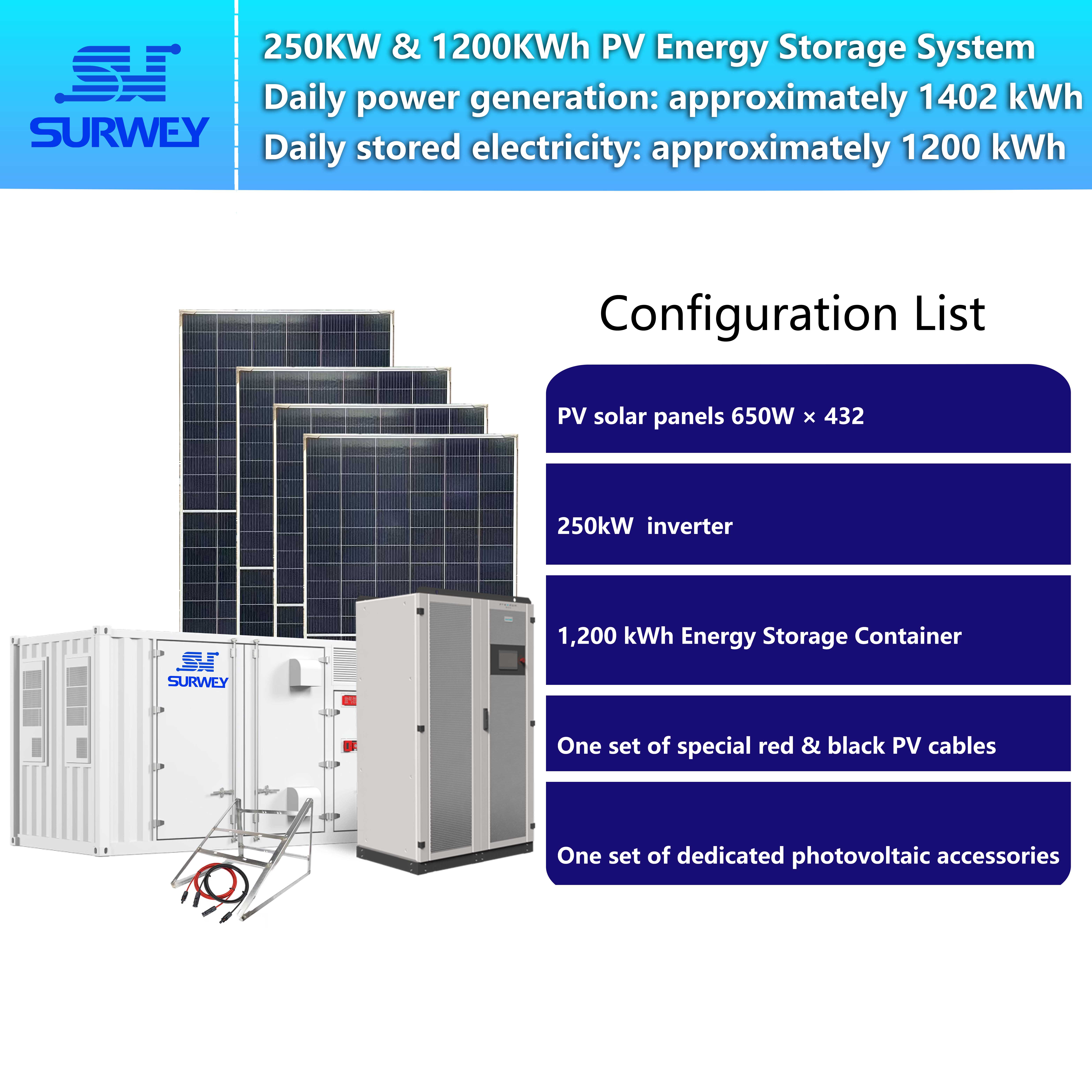
System Configuration Diagram
This case targets a commercial and industrial plant in the Middle East. It adopts a 250kW hybrid grid microgrid inverter + 1200kWh energy storage container + 432 pieces of 650W high-efficiency PV modules. The system supports grid-connected priority operation as well as off-grid microgrid operation. It enables self-consumption to reduce the plant’s electricity purchase cost, and guarantees uninterrupted power supply for critical loads during grid outages, balancing economic benefits and power supply reliability.
PV Array: 432 pieces of 650W N-type high-efficiency PV modules
Each module has an STC power rating of 650W, open-circuit voltage Voc=49.73V, maximum power point voltage Vmp=41.56V, short-circuit current Isc=16.63A, operating current Imp=15.65A. The total installed capacity of all modules is 280.8kWp. N-type modules feature excellent temperature coefficients, making them well-suited to the high-temperature environment of the Middle East and mitigating power degradation losses caused by high temperatures. Bifacial designs can also capture additional rear-side power gain using ground-reflected irradiance.
Core Inverter Equipment: 250kW microgrid hybrid inverter

Image of a 250 kW Microgrid Hybrid Inverter
This is a 480V output hybrid grid inverter supporting both grid-connected and off-grid modes with microgrid grid-forming capability. Its maximum PV input voltage is 1000V, and the MPPT operating voltage window ranges from 250V to 850V. The maximum allowable PV access power on the PV side is 300kW. It supports multi-unit parallel connection, is compatible with mainstream battery BMS communication protocols, and comes with built-in remote EMS monitoring and fault logging functions, meeting the unattended operation and maintenance requirements of overseas projects.
This model adopts a version with 6 independent MPPT modules. Each channel tracks voltage and current independently. When partial array shading occurs due to sand dust, overall power generation losses can be reduced.
Energy Storage Unit: 1200kWh outdoor energy storage container

Image of a 1,200 kWh Outdoor Energy Storage Container
The containerized energy storage system integrates battery clusters, BMS, fire protection system and temperature control air conditioning system. The 1200kWh capacity stores excess electricity generated by photovoltaics during daytime for plant production use at night. In cases of grid fluctuation or power failure, it cooperates with the inverter for fast switching to keep critical plant equipment running continuously. The container is prefabricated and integrated at the factory; on-site work only involves foundation construction and cable connection, greatly shortening overseas on-site construction cycles and reducing on-site commissioning workload. This is the primary reason why containerized energy storage is widely preferred for Middle East projects.
The system features a PV oversizing ratio of approximately 1.12 times: 280.8kWp PV against the inverter’s AC rated power of 250kW. Reasonable PV oversizing is common practice in high-irradiance regions of the Middle East. During peak irradiance at midday, the inverter moderately curtails power. In morning and afternoon hours with moderate irradiance, the oversized PV capacity can be fully utilized to boost annual power generation revenue. However, oversizing cannot be unlimited; it must stay within the inverter’s maximum allowable PV-side power of 300kW. The 280.8kWp in this project fully complies with the equipment limit.
II. PV String Electrical Design: Why 18 Modules per String and 24 Strings?
PV series string quantity is a frequent pitfall in overseas projects. Many designers simply calculate based on room-temperature parameters and ignore open-circuit voltage rise caused by low night-time temperatures in deserts. This results in DC voltage exceeding the inverter voltage withstand limit under low-temperature conditions, triggering overvoltage alarms and, in severe cases, inverter damage.
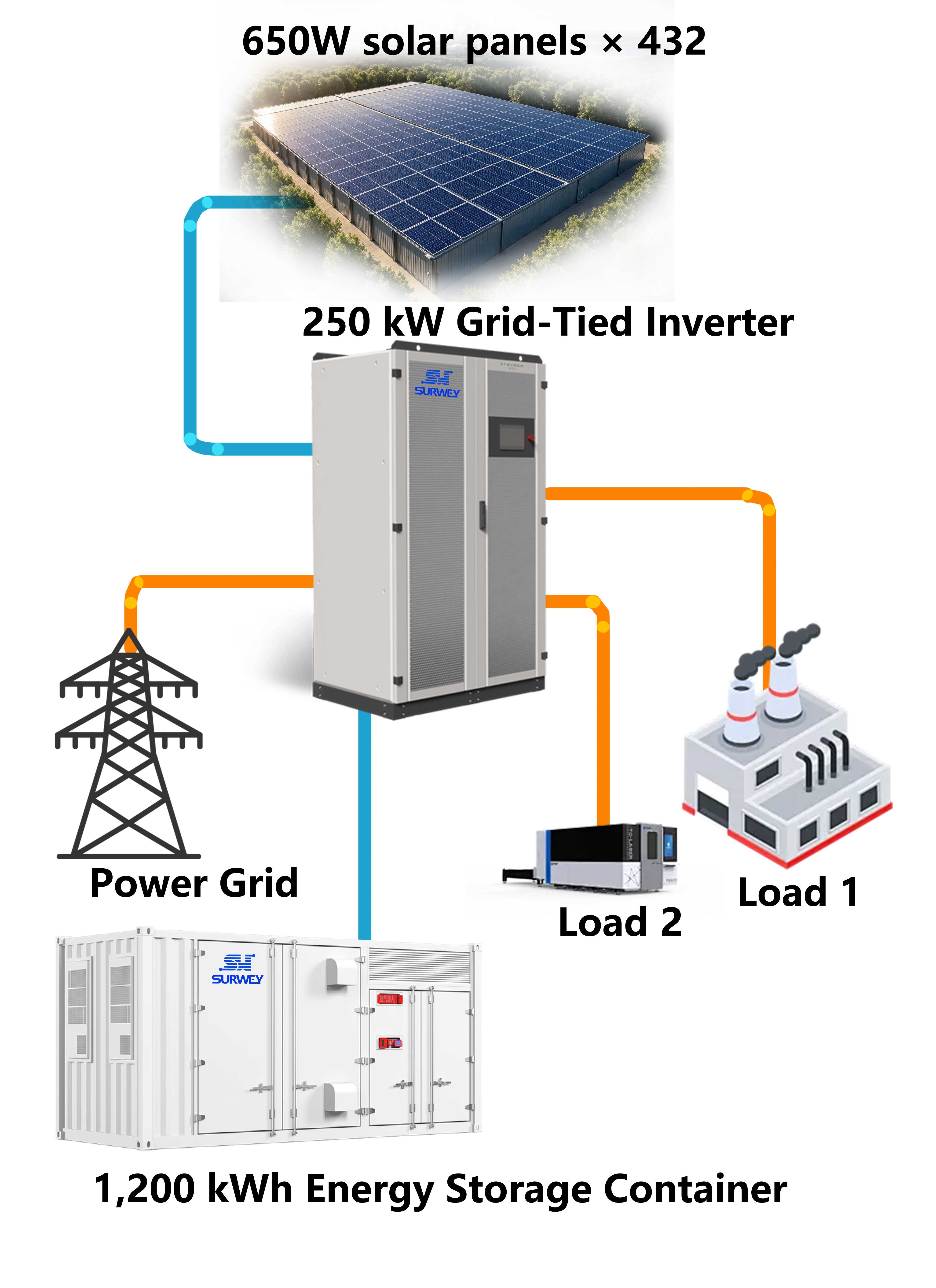
Schematic System Topology Diagram
There are 432 modules in this project. We first need a series count that divides evenly into 432 to ensure all strings are identical. Under a single MPPT channel, strings with different module counts must never be mixed. Mixed long and short strings will disrupt MPPT tracking, drastically reduce power generation efficiency and multiply troubleshooting difficulty in later stages. Given limited on-site O&M resources overseas, such hidden risks should be avoided as much as possible.
Calculation: 432 ÷ 18 = 24 strings, meaning 18 modules connected in series per string, forming 24 identical strings in total. Key voltage verification is carried out as follows:
- Maximum power voltage per string Vmp = 18 × 41.56V = 748.08V, falling within the inverter MPPT operating range of 250–850V for normal maximum power point tracking.
- Open-circuit voltage per string Voc = 18 × 49.73V = 895.14V, leaving ample safety margin below the inverter’s 1000V maximum DC withstand voltage. The desert in the Middle East sees huge diurnal temperature differences. Low night-time temperatures raise module open-circuit voltage. Even accounting for this low-temperature voltage rise, this configuration will not hit the 1000V equipment limit, ensuring sufficient safety.
Comparison with alternative series configurations:
- If 20 modules per string are selected: 432 divided by 20 yields 21 complete strings plus a remainder of 12 modules, creating long and short strings. The leftover short string must occupy a separate MPPT channel, leading to severely unbalanced MPPT loading. This is not recommended in engineering practice.
- If 16 modules per string are selected: 432 ÷ 16 = 27 strings. Voltage also complies with requirements, yet the total string count increases, raising quantities of combiner boxes, DC cables and fuses, and pushing up material and construction costs.
After comprehensive evaluation of voltage safety, even module division and material costs, the optimal solution is finalized: 18 modules connected in series per string, with 24 strings in total.
Next is MPPT branch allocation. The inverter uses the 6 independent MPPT version. 24 strings are evenly distributed, with 4 strings connected in parallel to each MPPT channel. MPPT1: 4 strings; MPPT2: 4 strings; MPPT3: 4 strings; MPPT4: 4 strings; MPPT5: 4 strings; MPPT6: 4 strings. Operating current per string is 15.65A. Four parallel strings deliver 62.6A operating current and 66.52A short-circuit current per MPPT channel, with 46.8kW PV power per channel, all within the inverter’s current and power bearing capacity for each MPPT.
Engineering wiring logic: Modules are connected in series to form strings, routed out via MC4 PV connectors and connected to DC combiner boxes. One DC combiner box corresponds to each MPPT channel. Combiner boxes are equipped with string fuses, DC disconnect switches and DC lightning protection SPD. DC cables from combiner boxes connect to the 6 MPPT DC terminals of the inverter.
Important note: The inverter has an IP20 protection rating and cannot be placed directly outdoors. It must be installed inside an equipment room or container cabin to isolate sand dust and intense sunlight. DC PV cables must adopt 1500V-grade high-temperature resistant PV-specialized cables. Ordinary cables will rapidly age and crack under long-term outdoor exposure in the Middle East, bringing safety hazards.
III. System Operation Logic Adapted to Actual Middle East Plant Conditions
This hybrid grid PV-ESS system supports multiple operating modes, which can be configured via the inverter backend during commissioning according to plant requirements.
Video of System Working Principle
Mode 1: Grid-connected self-consumption mode (primary daily operation) When solar irradiance is sufficient during daytime, photovoltaics supply plant production loads with priority. If PV generation exceeds plant consumption, surplus power is stored in the 1200kWh energy storage container. When PV output is lower than plant load demand, energy storage discharges to supplement power supply. If neither PV nor energy storage can meet the load, the system automatically draws power from the grid. This logic maximizes consumption of green power generated by PV and reduces grid electricity purchases to cut the plant’s power bills. Many regions across the Middle East feature prominent peak-valley electricity price differentials. Energy storage stores excess daytime PV power for discharge during high-price periods to further boost project revenue.
Mode 2: Off-grid microgrid mode during grid faults When the external grid suffers power outages or abnormal voltage/frequency, the inverter rapidly switches to off-grid grid-forming mode. PV and energy storage jointly support power supply for critical plant loads. At night with no PV input, the energy storage container maintains loads through discharge. When battery SOC drops to the preset lower limit, a diesel generator can be triggered as backup power to sustain uninterrupted production — highly suitable for Middle East plants with unstable grid conditions. Once the external grid returns to normal, the system automatically detects restoration and seamlessly switches back to grid-connected mode without on-site manual intervention.
Mode 3: Power curtailment, backup and other strategies Meanwhile, the inverter supports EMS remote monitoring. Operators can remotely view PV generation power, energy storage SOC, plant load power, and status of all AC/DC equipment. Fault alarms are pushed automatically, adapting to the reality of limited on-site personnel and remote maintenance for overseas projects. The BMS of the energy storage container communicates and interacts with the inverter to implement charge and discharge protection, preventing battery overcharging and over-discharging and protecting battery service life.
Reference for Off-Grid Load Capacity and Duration
Note: Data is based on a 1200kWh energy storage container and 250kW rated inverter. Battery depth of discharge is calculated at 85%. Two operating conditions are covered: night (no PV input) and daytime (with PV input), for preliminary project selection reference only.
| Operating Condition | Supported Load Power | Available Duration | Remarks |
|---|---|---|---|
| Night (no PV input) | 100kW | ~10h | Energy storage discharge only; for office, lighting and control equipment |
| Night (no PV input) | 180kW | ~5.7h | Full energy storage output; supports partial production equipment |
| Night (no PV input) | 250kW | ~4.1h | Inverter full power; only for short-duration critical loads |
| Daytime (with PV generation) | 250kW | Long-duration operation | PV + energy storage coordination; PV power used preferentially |
Remarks: Actual runtime is affected by ambient temperature, battery degradation and load fluctuation. On-site measurement shall prevail.
IV. Non-Negotiable Engineering Design Points for Middle East Desert Operating Conditions
Beyond hardware selection for desert projects, environmental adaptation details directly determine equipment service life and power generation yield.
- High temperatures cause power derating for inverters and energy storage systems. Ensure adequate ventilation and heat dissipation for inverter rooms, and avoid direct noon sunlight on energy storage containers to keep cabin temperature control systems working properly. Select N-type modules with low temperature coefficients to alleviate high-temperature power degradation.
- Dust accumulation significantly reduces power generation revenue. Optimize support tilt angle according to local latitude and establish a regular module cleaning schedule. Equipment rooms and combiner boxes shall have dust-proof sealing to prevent fine sand ingress and equipment failure.
- Soil resistivity tends to be high in deserts. Complete earthing and lightning protection design shall be implemented for the whole system, with surge protection devices deployed separately on DC and AC sides. Outdoor cables and MC4 connectors must adopt UV-resistant and high-temperature-rated products to withstand repeated thermal expansion and contraction between day and night.
- Lock in key parameters during overseas procurement, especially configurable hardware such as MPPT channel quantity. All items shall be incorporated into technical agreements as acceptance criteria. PV oversizing requires rational design rather than unlimited increase, to avoid extra failure risks under long-term high-current operation.
V. Project Value Summary and Reflections on Overseas Projects
When talking about the Middle East market, most people immediately think of abundant solar resources and high returns for PV projects. However, practitioners with hands-on project delivery experience know that desert environments impose stringent requirements on system design, equipment selection, construction and O&M. Simply copying mature domestic solutions cannot guarantee success.
This 250kW hybrid grid commercial and industrial PV-ESS system, equipped with 280.8kWp PV modules and a 1200kWh energy storage container, fully combines inverter hardware parameters and local climatic conditions starting from PV string sizing. All strings maintain consistent parameters and MPPT loading is balanced. It enables self-consumption under grid-connected operation to cut plant electricity costs, and delivers off-grid microgrid capability to mitigate grid instability risks, achieving both economic benefits and power supply security.
For overseas EPCs and project developers undertaking Middle East PV-ESS projects, do not rely merely on attractive parameters from product brochures. Environmental temperature, low-temperature open-circuit voltage, MPPT allocation, equipment version differences, dust-related O&M, earthing and lightning protection must all be defined in drawings and procurement agreements. Many troubles arising in later project stages stem from minor oversights in preliminary design.
New energy export competition is not only about equipment pricing, but about translating theoretical solutions into field-engineered systems that operate stably for years under complex local operating conditions.


