
Technical Proposal for a Photovoltaic Energy Storage System at an Aluminium Alloy Door and Window Manufacturing Plant in the UAE
Foreword
The UAE enjoys abundant sunlight, but electricity tariffs for industry and commerce are relatively high. Furthermore, the power grid in industrial estates is subject to voltage fluctuations and occasional brief power cuts. In the event of a sudden power cut, the unexpected shutdown of critical cutting and spraying equipment can result in the scrapping of profiles and the interruption of production processes, causing direct financial losses to the enterprise. To reduce the factory’s costs of purchasing electricity from the grid, achieve peak-shaving and off-peak charging, and simultaneously enhance the reliability of the site’s power supply, this project involves the construction of a grid-connected photovoltaic-storage hybrid system.
I.🏭 Project Overview
This project is based at an aluminium alloy door and window manufacturing plant within an industrial estate in the United Arab Emirates. The plant’s primary production activities include the cutting, punching, corner joining, powder coating and assembly of finished doors and windows. High-power processing equipment in the production workshop operates primarily during the day, from 08:00 to 18:00, making it a typical high-load commercial and industrial user during daytime hours.
The system primarily comprises a rooftop photovoltaic array, a 50 kW three-phase hybrid inverter-controller unit and a 112 kWh rack-mounted high-voltage lithium iron phosphate energy storage battery system. It enables the generation and self-consumption of photovoltaic electricity, the storage of surplus energy, and the switching to a backup power supply mode in the event of a grid failure.
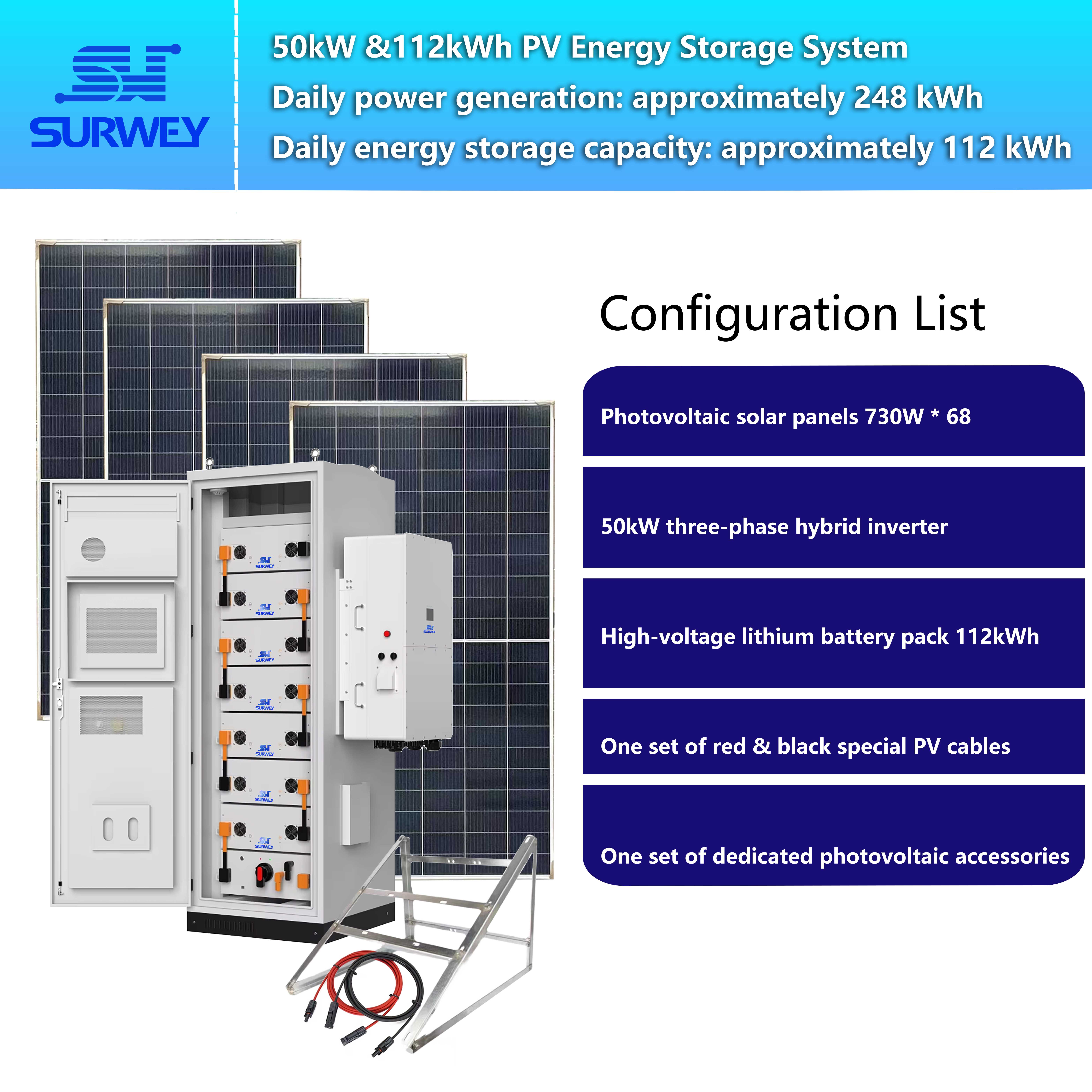
The entire system is fully adapted to the tropical desert climate of the United Arab Emirates, characterised by high temperatures, intense sunlight and frequent sandstorms, and makes full use of unused space on factory roofs, whilst not occupying valuable production or storage space within the factory premises.
II. 📐Description of the site and installation environment
The photovoltaic array for this project is entirely installed on the roof of the processing plant’s existing steel-framed building, without occupying any land in the ground-level production workshops, raw material storage areas or finished goods warehouses, thereby maximising the utilisation of the site’s idle roof space. The factory roof consists of a steel-framed colour-coated steel structure; its load-bearing capacity meets the requirements for installing photovoltaic module mounting frames. The roof is unobstructed, with no tall structures or surrounding buildings or chimneys to block sunlight, ensuring excellent sunlight reception conditions throughout the year, making it highly suitable for distributed photovoltaic development.
The photovoltaic modules are installed flat on roof-mounted racks, which are raised to provide ventilation and heat dissipation gaps. This not only reduces the operating temperature of the modules and improves power generation efficiency but also minimises the accumulation of wind-blown sand and dust on the rear of the modules, facilitating future access by operations and maintenance personnel for cleaning and inspection work on the roof.


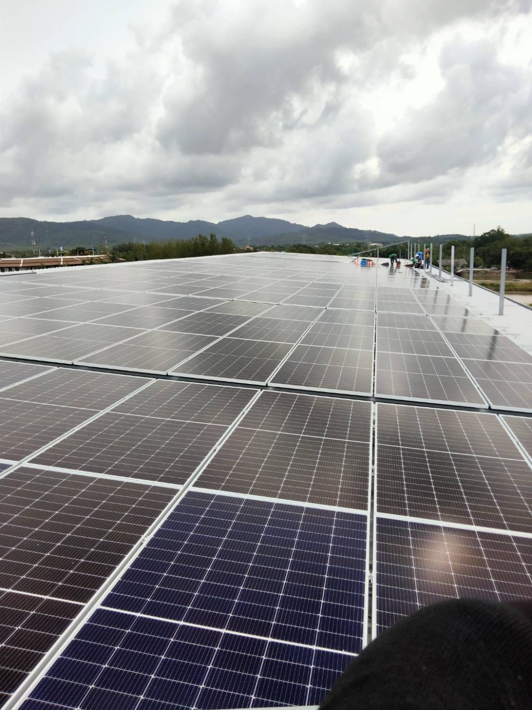
Flat-lay installation of roof supports
The energy storage battery system is installed in a rack-stacked configuration within a dedicated, well-ventilated plant room on the factory premises, away from dust and heat sources in the production and spray painting workshops, and protected from direct sunlight; the inverters are installed close by on the external wall of the plant room to minimise the length of the DC cabling, thereby reducing losses in the DC circuit, whilst also facilitating future inspections and maintenance.


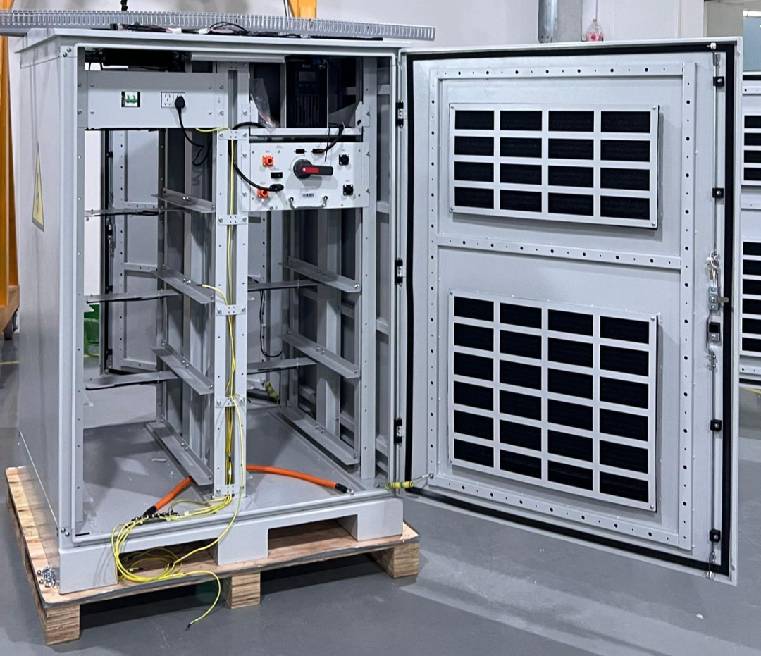
Placement of energy storage battery cabinets
The layout of the entire system has been designed to integrate fully with the factory’s existing building layout, without altering the original production processes; as a result, normal production operations at the factory will be virtually unaffected during the project’s construction phase.
III. ⚙️ Selection of Key Equipment
☀️Photovoltaic modules
The project utilises 730W N-type monocrystalline silicon photovoltaic modules, which are optimised for high-temperature regions. Key electrical parameters include: open-circuit voltage (Voc) of 50.54V under standard test conditions (STC), maximum operating voltage (Vmp) of 42.47V, and peak operating current (Imp) of 17.21A. The modules feature high conversion efficiency and minimal power degradation under high-temperature conditions.
The module junction box has an IP68 protection rating, offering excellent resistance to wind, sand, humidity and heat; the open-circuit voltage temperature coefficient is –0.24%/°C, meaning that the open-circuit voltage increases as the temperature decreases, which is a key parameter for safety verification in DC systems. A total of 68 730W photovoltaic modules have been installed for this project.


🔌Combined mixing and reverse control unit
A 50 kW three-phase hybrid inverter-controller unit has been selected to serve as the core control unit for the entire photovoltaic-storage system.


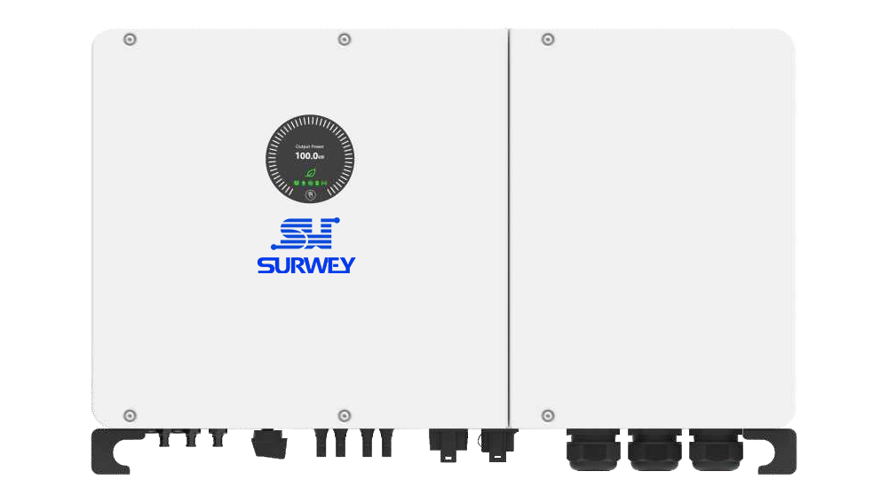
50 kW three-phase grid-tied inverter
The unit is equipped with four mutually independent MPPT channels, with an MPPT operating voltage range of 620–850 V and a maximum permissible open-circuit voltage on the PV side of 1,000 V; it supports direct DC connection to high-voltage energy storage batteries, and integrates grid-connected, off-grid UPS and black start functions, whilst supporting 100% three-phase unbalanced output; The unit can operate without derating at an ambient temperature of 50°C, making it suitable for the extreme summer heat in the Middle East; it supports operation on weak grids with SCR < 1.2, is compatible with voltage fluctuations typical of industrial area grids in the UAE, and perfectly matches the power consumption characteristics of three-phase processing loads in aluminium alloy processing plants. The unit has an IP66 protection rating and is resistant to sand and dust when installed outdoors.
🔋Energy Storage Battery Systems
The energy storage system has a total available capacity of 112 kWh, comprising seven 16 kWh rack-mounted lithium iron phosphate battery modules connected to a high-voltage combiner box; the battery type is LiFePO₄.


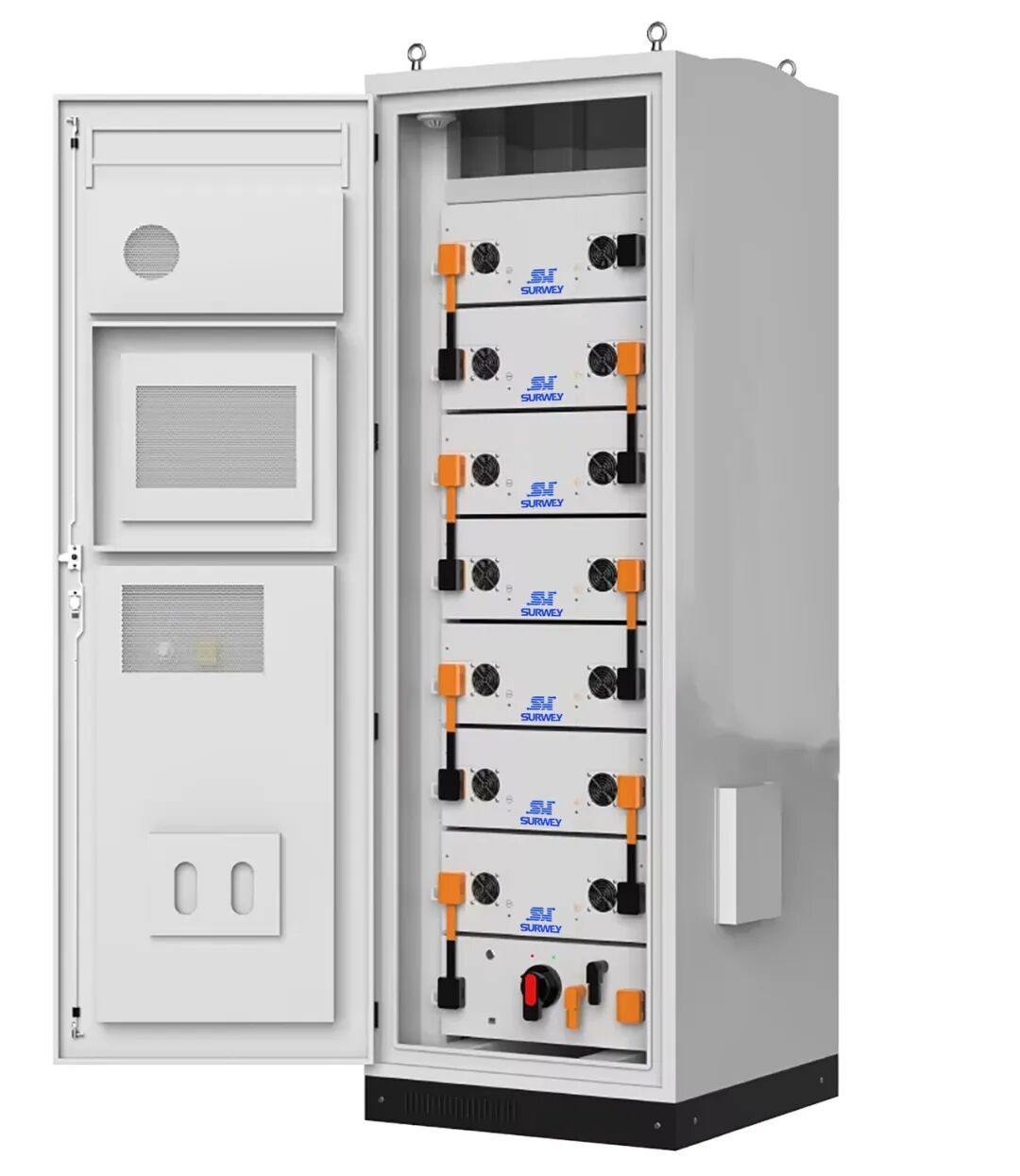
112 kWh energy storage battery cabinet (16 kWh × 7)
The battery system is equipped with a comprehensive BMS (Battery Management System), featuring overvoltage, undervoltage, overcurrent and overtemperature protection. It interfaces with the inverter via CAN 2.0/RS485 communication protocols to enable coordinated management of charging and discharging.
The battery cycle life is ≥8,000 cycles (at 25°C, 0.5C charge/discharge rate, 90% DOD), with a long design service life and a 5-year warranty; The system’s operating voltage range falls within the inverter’s battery input range of 310–800 V, with charging and discharging power matched to the capacity of a 50 kW inverter.
The battery pack is stacked in a rack-mounted configuration and installed in an indoor equipment room to avoid exposure to high temperatures and direct sunlight, ensuring long-term stable operation of the batteries.
IV. 🧮 Series and Parallel Configurations of Photovoltaic Arrays and Electrical Safety Verification
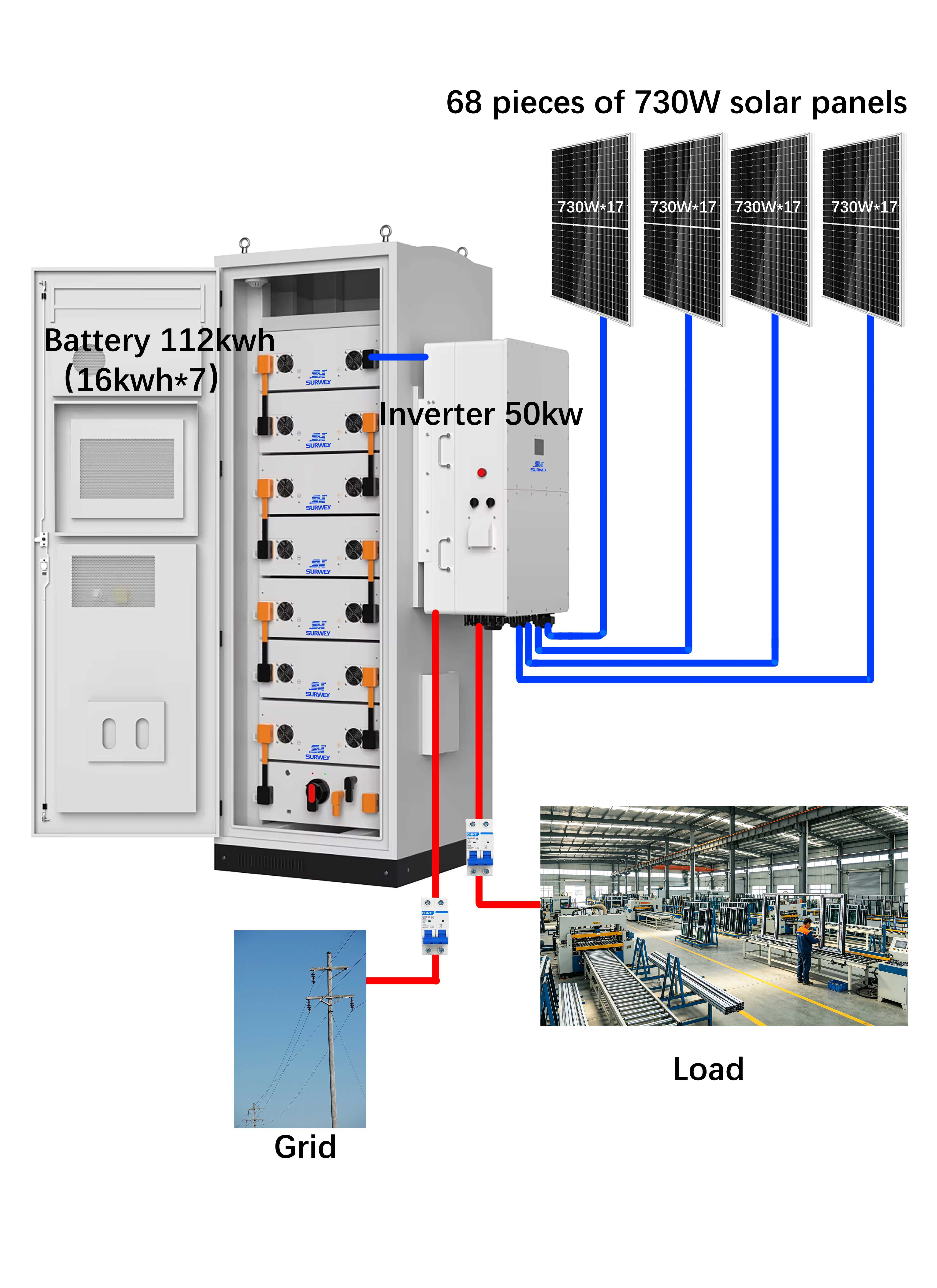
Wiring scheme for the photovoltaic array in this project: 17 modules are connected in series to form one string; there are four strings in total, comprising 68 modules. The four strings are connected to the inverter’s four independent MPPT channels respectively.
1) Calculation of the optimal operating voltage per string: Vmp string = 17 × 42.47 V = 721.99 V. This voltage falls within the inverter’s MPPT operating voltage range of 620–850 V, enabling the inverter to continuously and stably track the maximum power point, thereby ensuring power generation output.
2) Low-temperature open-circuit voltage verification: The minimum ambient temperature during winter nights in the UAE is taken as 10 °C. As the temperature decreases, the module’s open-circuit voltage increases, representing the most hazardous operating condition for the DC system. Temperature difference ΔT = 10 – 25 = –15 °C. Low-temperature open-circuit voltage per module = 50.54 × [1 – 0.0024 × (-15)] = 52.36 V. The maximum low-temperature open-circuit voltage for the entire string = 17 × 52.36 V = 890.12 V. The maximum withstand voltage on the PV side of the inverter is 1,000 V; as 890.12 V < 1,000 V, the DC-side voltage is safe and will not cause an inverter failure due to overvoltage breakdown. If the number of modules in series were increased to 18, the low-temperature open-circuit voltage would exceed the equipment’s voltage withstand limit, posing a significant safety hazard; therefore, this scheme strictly adheres to a configuration of 17 modules in series.
3) Power and Current Verification Total installed PV power: 68 × 730 W = 49.64 kW. The inverter’s maximum PV input power is 100 kW, providing ample power redundancy. The operating current per string is 17.21 A. With each of the four MPPT channels connected to a single string, the input current per MPPT channel is well below the maximum current limit of 50 A. As the four MPPT channels operate independently of one another, minor dust accumulation on some rooftop modules or temporary localised shading will not result in power loss across the entire array, thereby enhancing the system’s overall fault tolerance.
4) Power Generation Parameters: Leveraging the UAE’s excellent solar irradiation resources, the system’s average daily photovoltaic power generation is 248 kWh; the energy storage battery has a rated capacity of 112 kWh, with a maximum daily storage capacity of 112 kWh. During the day, photovoltaic power is prioritised to supply the factory’s production equipment, such as cutting and corner-joining machines, whilst any surplus power is stored in the energy storage batteries; in the evening, as sunlight diminishes and photovoltaic output becomes insufficient, the energy storage batteries discharge electricity to supply the factory premises, thereby reducing consumption of the mains grid during peak hours.
V. 🔄 System Operational Logic
Video: Diagram illustrating the direction of current flow during system operation
1.⛅ Photovoltaic Priority Mode (Daytime Grid-Connected Operation)
During periods of ample sunlight, the photovoltaic array outputs direct current (DC) to the 50 kW hybrid inverter-controller unit. The system’s control logic prioritises the supply of photovoltaic power to the factory’s production loads, meeting the electricity requirements of profile cutting, punching and assembly equipment; when the photovoltaic power output exceeds the factory’s real-time electricity demand, the surplus energy is used to charge the 112 kWh energy storage battery until it reaches full capacity.
2.🌙 Energy Storage Discharge Peak-Shaving Mode (Evening / Peak Demand Periods)
As the sun’s altitude decreases, PV output gradually declines. When PV generation is insufficient to support the factory’s electricity consumption, the energy storage battery begins to discharge. The energy is converted by the inverter into three-phase AC power to supply the factory’s loads, replacing high-cost grid electricity. This achieves peak-shaving and valley-filling, thereby reducing the factory’s electricity bills.
3.⚡ UPS Backup Power Supply Mode (Grid Failure)
When the grid is operational, the system operates in grid-connected mode; should a power cut occur in the industrial estate’s grid, the inverter rapidly switches to off-grid UPS backup mode to provide emergency power to the factory’s critical production equipment, supporting black start functionality. Once the mains grid returns to normal, the system automatically detects this and seamlessly switches back to grid-connected mode, ensuring production continuity and minimising losses from scrap profiles caused by power outages.
4.Adaptive Operation in Weak Grid Conditions
The inverter supports weak grid conditions with SCR < 1.2 and is capable of adaptive adjustment to voltage fluctuations in the UAE’s industrial zone grid; it also supports 100% three-phase unbalanced output, accommodating the actual on-site conditions of three-phase load imbalance caused by the start-up and shutdown of equipment in door and window processing factories.
VI. 🌡️Design for Environmental Adaptation and Operations and Maintenance in the UAE
The United Arab Emirates has a tropical desert climate, characterised by extremely high ambient temperatures in summer and high levels of dust in the air, which place significant demands on the weather resistance of photovoltaic energy storage equipment. This solution has been specifically designed to address these challenges:
1. High-temperature adaptability
The inverter supports output without derating at 50°C; the photovoltaic mounting structure is elevated to improve ventilation, reducing the operating temperature of the modules and minimising high-temperature power degradation; the energy storage batteries are housed in an indoor equipment room to avoid direct sunlight, thereby safeguarding their charging and discharging performance and service life.
2. Protection against Wind and Sand
The photovoltaic modules have an IP68 protection rating and the inverters an IP66 rating, preventing sand and dust from entering the electrical compartments; the roof-mounted mounting structure facilitates regular dust removal from the module surfaces, minimising power generation losses caused by dust accumulation.
3. Electrical Safety Protection
A 17-cell series connection is strictly implemented in accordance with verification results, eliminating the risk of DC overvoltage; All DC cables are specialised weather-resistant photovoltaic cables, and comprehensive earthing and lightning protection are provided on the roof and in the equipment room.
4. Ease of Operation and Maintenance
Inverters and batteries are centrally located, with sufficient space reserved for maintenance operations; the system supports remote data monitoring, allowing remote viewing of power generation data and battery SOC status, which enables O&M personnel to monitor system operation and reduces the frequency of on-site inspections.
VII. 📊 The system can generate a summary table showing the power ratings of connected equipment and their backup durations
Note: The total capacity of the energy storage batteries is 112 kWh; based on a depth of discharge (DOD) of 90 per cent, the actual usable energy is 100.8 kWh; the inverter’s maximum AC backup output is 50 kW.
| Item | Parameter |
|---|---|
| Available Energy Storage Capacity | 100.8 kWh |
| Inverter Max. Backup Output Power | 50 kW |
| Theoretical Backup Duration with Full 30kW Door & Window Processing Load | approx. 3.36 h |
| Theoretical Backup Duration with 20kW Main Production Equipment | approx. 5.04 h |
| Theoretical Backup Duration with 10kW Critical Core Equipment | approx. 10.08 h |
| PV System Installed Capacity | 49.64 kW |
| Average Daily PV Power Generation | 248 kWh |
| Max. Daily Energy Stored | 112 kWh |
VIII. ✍️ Summary of the Proposal
This solar-storage system has been custom-designed to suit the production characteristics of an aluminium alloy door and window manufacturing plant in the United Arab Emirates, as well as the site’s architectural conditions and local climate and grid conditions. The 49.64 kW photovoltaic array is installed entirely on the rooftops of disused factory buildings, thus occupying no ground-level production or storage space; 68 x 730 W modules are configured in strings of 17, with four strings connected to four independent MPPT trackers respectively. Following voltage verification under extreme low-temperature operating conditions, the operating voltage falls entirely within the inverter’s MPPT range, ensuring electrical safety and reliability.
The system is complemented by a 112 kWh long-cycle lithium iron phosphate energy storage battery with a cycle life of ≥8,000 cycles, serving the dual functions of self-generation and self-consumption during the day to manage peak demand, and providing emergency backup power in the event of a grid failure. The system not only makes full use of the region’s abundant sunlight to reduce the factory’s electricity procurement costs but also provides varying levels of backup power duration for processing equipment during power cuts, thereby mitigating production losses caused by sudden power outages. The entire solution features hardware with strong weather resistance, adapted to the high-temperature, sandy environment of the UAE. With a mature operation and maintenance plan, it balances the project’s economic benefits with the reliability of production power supply, making it highly suited to the practical application needs of commercial and industrial factories in the Middle East.


