
Technical Solution for a 30 kW Integrated Photovoltaic and Energy Storage System for Commercial and Industrial Applications
I. Project Overview and Design Objectives
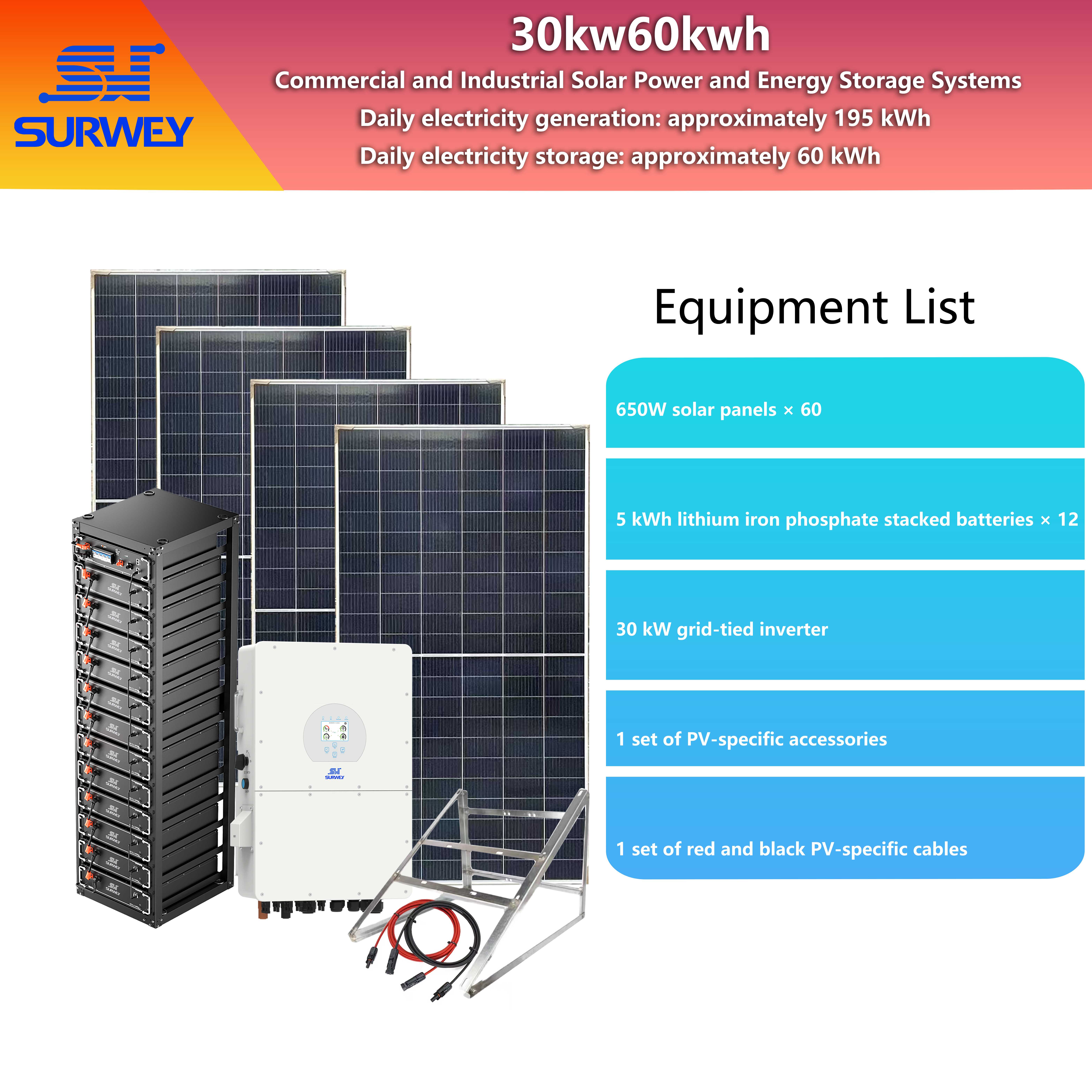
The solution adopts the industry-standard high-voltage DC common bus architecture, connecting both photovoltaic modules and energy storage batteries to the DC side of the inverter. This maximally simplifies the system structure and reduces power transmission losses. It not only meets the enterprise’s continuous power needs for daily production and operations and significantly reduces the cost of purchasing electricity from the grid, but also generates additional revenue through a strategy of charging during off-peak hours and discharging during peak hours. Additionally, it provides seamless switching capabilities in the event of grid abnormalities, ensuring the uninterrupted operation of core production equipment. The entire system design strictly adheres to industry safety and performance standards. All core equipment parameters are precisely matched without redundant configurations. While meeting daily average power generation targets, the system achieves an optimal balance between investment and long-term returns and is suitable for a variety of installation scenarios, including commercial and industrial rooftops and ground-mounted installations.
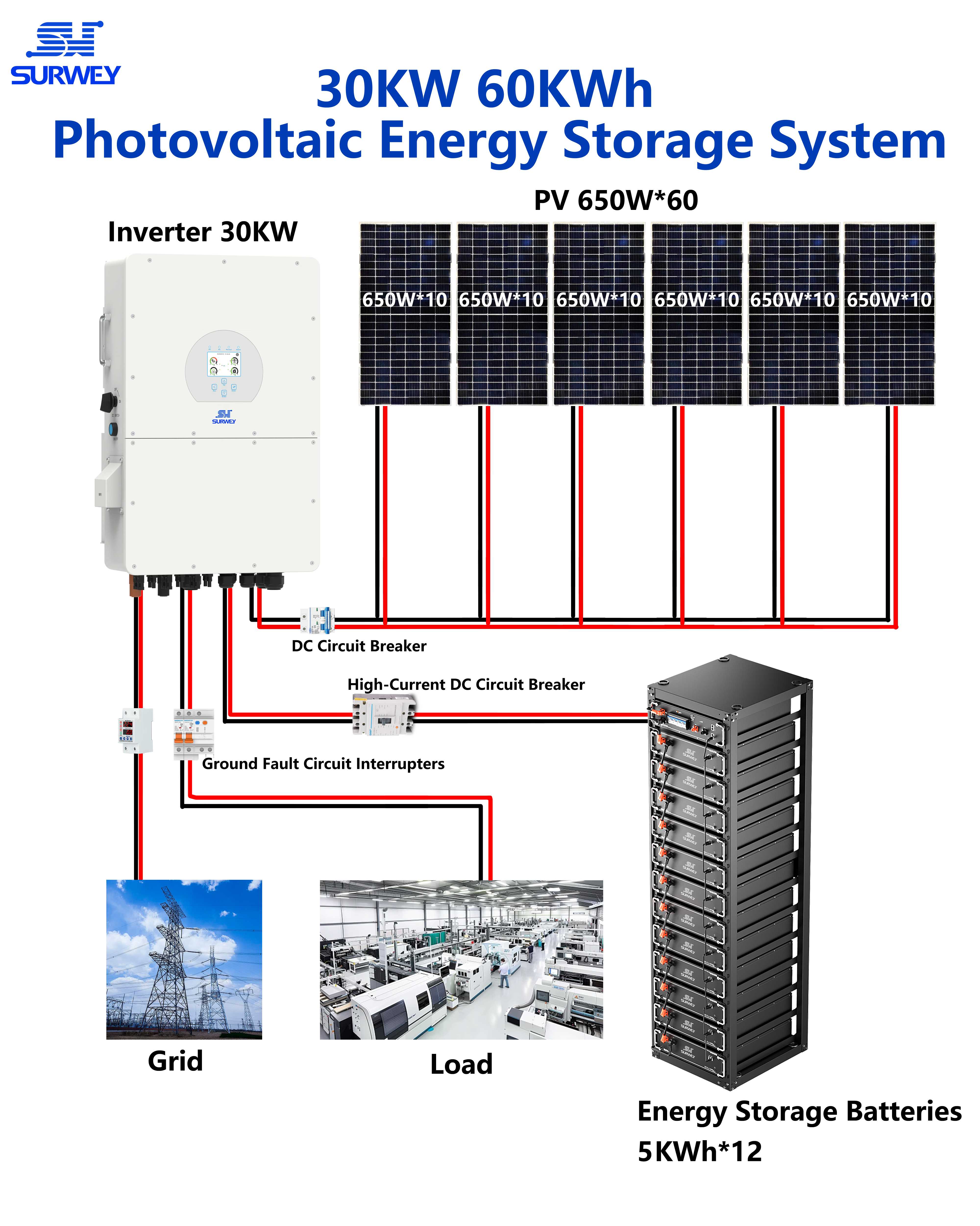
Topology Diagram of a 30 kW/60 kWh Commercial and Industrial Photovoltaic Energy Storage System
II. Overall System Architecture and Technical Approach
This system adopts an integrated topology comprising a “PV array + energy storage battery pack + high-voltage energy storage inverter + power grid + local loads.” Its core technological approach—high-voltage DC transmission, MPPT (Maximum Power Point Tracking), and bidirectional AC/DC coordinated control—enables full-scenario coverage of efficient PV power conversion, intelligent energy storage charging and discharging, and grid-friendly interaction.
The photovoltaic array converts solar energy into direct current (DC) power and, through an optimized series-parallel design, connects directly to the MPPT input terminals of the inverter. The inverter’s built-in MPPT algorithm tracks the maximum power point of the modules in real time, ensuring maximum power generation efficiency under varying light intensities and ambient temperatures; The energy storage battery bank is connected in parallel to the DC side of the inverter and shares a DC bus with the PV array. It stores surplus PV energy or electricity drawn from the grid during off-peak hours, and supplements power to local loads when PV generation is insufficient, during grid peak hours, or in the event of grid abnormalities; The AC side of the inverter is connected to the facility’s low-voltage distribution panel, enabling bidirectional power transfer between the grid and local loads. It also integrates comprehensive protection and control functions, automatically switching operating modes based on sunlight intensity, electricity demand, and grid status to ensure safe and stable system operation under all conditions.
Compared to traditional AC-coupled architectures, this design significantly reduces the number of AC-to-DC conversion stages, thereby lowering energy conversion losses and the number of potential failure points. At the same time, high-voltage DC transmission reduces line current, minimizes cable selection costs, and decreases line losses. The system’s overall conversion efficiency can be improved by 3%–5%, making it better suited for high-power PV-storage applications in commercial and industrial settings.
III. Selection of Core Equipment and Verification of Parameter Matching
(1) Photovoltaic Array Design and Electrical Parameter Verification
Module Selection: High-efficiency N-type bifacial double-glass photovoltaic modules are selected, with a peak power of 650 W per module and a conversion efficiency of at least 23%. These modules feature excellent low-light performance, low degradation, and weather resistance, enabling long-term stable operation at ambient temperatures ranging from -40°C to 85°C. Their power output remains at no less than 85% of the initial value for 25 years, meeting the complex environmental requirements of outdoor, open-air installations in commercial and industrial settings.
Series-Parallel Optimization Design: Taking into account the inverter’s MPPT voltage range, the modules’ electrical characteristics, and grid connection capacity, the PV array is designed using a “10 modules in series + 6 strings in parallel” layout, with the number of modules per string limited to 10. total installed capacity = 650 W/module × 10 modules/string × 6 strings = 39 kWp, with a 1.3:1 ratio to the inverter’s rated AC power. This aligns with standard industry design ranges, ensuring full-load utilization of the inverter under varying irradiance conditions while avoiding module power redundancy, thereby achieving a balance between power generation efficiency and equipment investment.
Verification of voltage matching compliance: The open-circuit voltage of a single module under standard test conditions is 41.5 V; when 10 modules are connected in series, the open-circuit voltage of a single string is 415 V. The inverter’s MPPT voltage operating range spans 160 V to 1,000 V. The open-circuit voltage of a single string is well below the safety upper limit of 1,000 V and above the MPPT lower operating limit, fully covering the MPPT operating range. This ensures that the modules can still operate at the maximum power point under low-light conditions, such as at sunrise and sunset, thereby maximizing power generation efficiency. Furthermore, considering that the open-circuit voltage of the modules increases slightly in low-temperature environments, even under extreme low-temperature conditions, the maximum open-circuit voltage per string does not exceed 480 V. This remains within the inverter’s safe operating range, eliminating the risk of overvoltage damage and fully meeting the equipment’s operational requirements.
(2) Selection of Energy Storage Systems and Verification of Voltage Compatibility
This solution opts for a 5 kWh small-capacity battery pack rather than a 16 kWh large-capacity battery pack, with the primary goal of ensuring high system stability and the reliability of critical applications. The modular design of the smaller battery packs offers greater flexibility, allowing for precise matching to load requirements. The impact of a single-pack failure is minimal, providing higher redundancy and more precise charge/discharge control. This perfectly meets the uninterrupted power supply needs of critical commercial and industrial loads, significantly reducing the risk of single-point failures. Ultimately, high-voltage rack-mounted lithium iron phosphate (LiFePO₄) energy storage battery packs were selected, with a rated capacity of 5 kWh per pack, with 12 modules connected in series to achieve a total system capacity of 60 kWh and a rated voltage of 614.4 V. These modules feature a cycle life of no less than 8,000 cycles, high safety, a wide operating temperature range, and a low self-discharge rate. They meet the DC-side connection requirements of high-voltage energy storage inverters, enabling high-current rapid charging and discharging to satisfy all-scenario usage needs, including daily peak-valley arbitrage, capacity backup, and emergency power supply.
Voltage Matching and Startup Capability Verification: The inverter’s battery-side operating voltage range is 600 V to 800 V. With a battery pack rated voltage of 614.4 V, it falls entirely within the inverter’s operating voltage range, ensuring perfect compatibility between the battery and the inverter. This eliminates the need for an additional DC boost converter, significantly simplifying the system architecture. Additionally, the inverter’s battery startup voltage requirement is no less than 600 V, and the battery pack’s minimum operating voltage is no less than 600 V, fully meeting the voltage requirements for inverter startup and operation. This ensures the system can start up and operate stably at any time within the battery’s normal voltage range. The battery pack and inverter are connected via dedicated high-voltage DC cables, which are optimized for high-voltage DC transmission characteristics, effectively reducing line losses and improving the system’s overall efficiency.
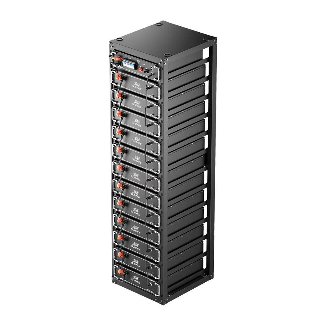
High-Voltage Rack-Mounted Lithium Iron Phosphate Energy Storage Battery Pack, 60 KWh
(3) Inverter Selection and Grid Connection Capability Verification
Inverter Selection: A three-phase high-voltage energy storage inverter with a rated AC output power of 30 kW is selected. It features two independent MPPT tracking channels and a conversion efficiency of at least 98%. meeting the connection requirements for high-voltage DC photovoltaic modules and energy storage batteries. It integrates comprehensive overvoltage, overcurrent, short-circuit, and islanding protection functions along with intelligent control algorithms, enabling four-party coordinated control of the PV system, energy storage, the utility grid, and the load, and meeting all technical requirements for commercial and industrial grid-connected applications.
Verification of Connection Capacity Compliance: Each MPPT channel of the inverter supports a maximum of 3 strings of modules, and the two MPPT channels combined support a maximum of 6 strings. The 6-string module configuration in this design exactly matches the inverter’s maximum string capacity, fully aligning with the inverter’s connection capabilities. This eliminates the need for an additional DC combiner box, significantly reducing system failure points and line losses. The inverter is equipped with an independent MPPT tracking algorithm, which enables independent maximum power point tracking for each string of modules. This effectively prevents power mismatch issues between module strings, maximizes the power generation efficiency of each string, and ensures long-term, stable system output.

30 kW Three-Phase High-Voltage Energy Storage Inverter
IV. System Operating Modes and Control Logic
Self-Generation and Self-Consumption with Excess Power Storage Mode
During daylight hours when sunlight is abundant, the electricity generated by the photovoltaic array is primarily supplied to local loads. When photovoltaic generation exceeds the electricity demand of local loads, the surplus electricity is automatically stored in the energy storage battery bank; when photovoltaic generation is insufficient to meet local load demand, the energy storage battery bank automatically discharges to supplement the supply, thereby achieving full on-site consumption of photovoltaic power and minimizing the cost of purchasing electricity from the grid.
Peak-to-Off-Peak Arbitrage Charging and Discharging Mode
Under the grid’s peak-off-peak electricity pricing policy, during off-peak hours at night, if the battery’s SOC falls below a preset threshold, the system automatically draws power from the grid to charge the battery pack; during peak hours in the daytime, the battery pack automatically discharges to supply local loads, thereby avoiding the need to purchase electricity at higher prices during peak hours and generating a stable return by leveraging the difference between peak and off-peak electricity rates.
Emergency Off-Grid Power Supply Mode
In the event of an unexpected power outage, the system can perform a seamless switchover within milliseconds, automatically entering off-grid operation mode, where the photovoltaic array and energy storage battery bank jointly supply power to local critical loads, ensuring the uninterrupted operation of production equipment. Once grid power is restored, the system automatically switches back to grid-connected operation mode without requiring manual intervention, enabling fully automated, intelligent control throughout the entire process.
MPPT (Maximum Power Point Tracking) Mode
The inverter’s built-in MPPT algorithm monitors the output voltage and current of each module string in real time and automatically adjusts the operating point to ensure that the modules deliver maximum power under any lighting conditions, maximizing power generation efficiency even in low-light scenarios such as cloudy days or during early morning and late evening when light is weak.
V. Estimation of Electricity Generation and System Efficiency
This plan is designed to generate an average of 195 kWh per day. The calculation basis and key parameters are as follows:
Basic Parameters: Total installed capacity of the PV array is 39 kWp; the peak power of each module under standard test conditions is 650 W; the effective light-receiving area and conversion efficiency of each module comply with industry standards.
Effective Operating Hours: Taking into account the project site’s average annual solar radiation, the modules’ low-light response characteristics, and the impact of ambient temperature, the average daily effective operating hours are designed to be no less than 5 hours. The average daily power generation = 39 kW × 5 hours = 195 kWh, which fully aligns with the design target.
Overall System Efficiency: The overall system efficiency is calculated at 85%, accounting for all factors including module matching losses, line losses, inverter conversion losses, and dust shading losses. The actual average daily effective electricity output is no less than 165 kWh, which fully meets the daily electricity needs of small and medium-sized commercial and industrial enterprises. Annual electricity generation is no less than 58,000 kWh, with a cumulative power generation of no less than 1.4 million kWh over 25 years, ensuring long-term and stable power generation revenue.