
40 kW/80 kWh Commercial and Industrial Solar Power and Energy Storage System Technical Solution
Operating Principles of a 40 kW/80 kWh Commercial and Industrial Solar Photovoltaic Energy Storage System
I. Project Overview
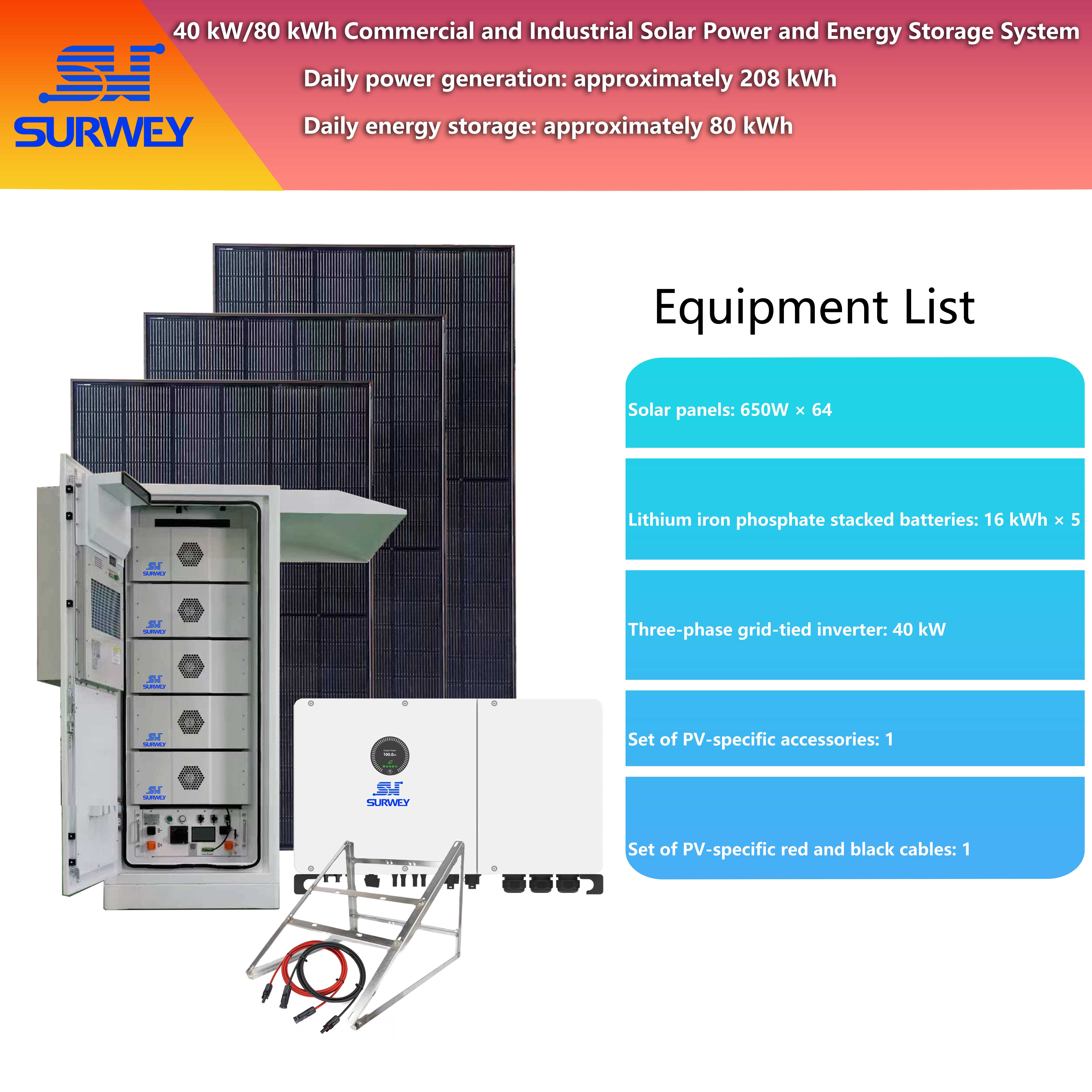
40 kW/80 kWh Commercial and Industrial Solar Power and Energy Storage System Configuration Diagram
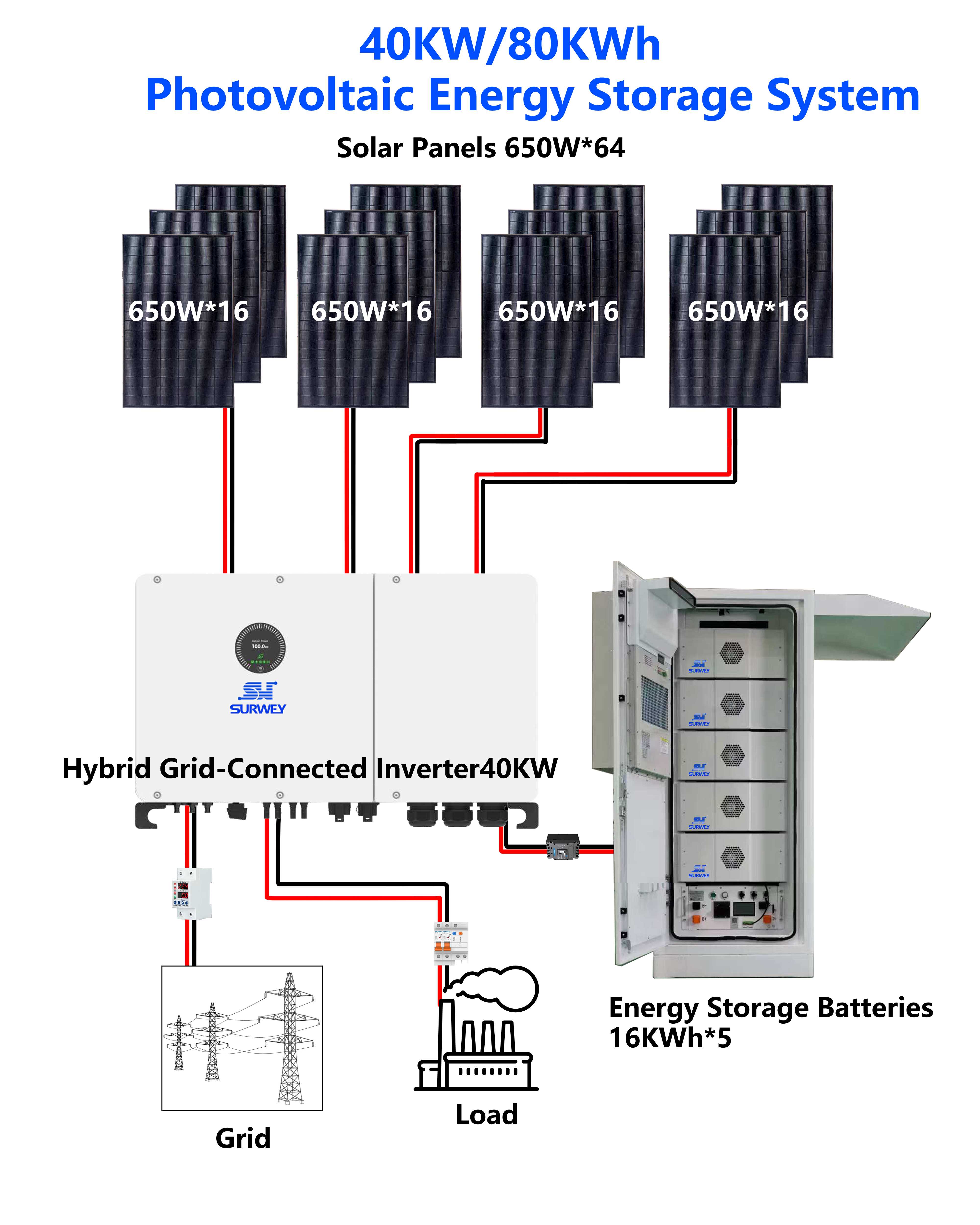
Topology Diagram of a 40 kW/80 kWh Commercial and Industrial Solar Power and Energy Storage System
II. System Design Principles
Principle of Efficiency
Core equipment consists of industry-leading, high-efficiency products. The conversion efficiency of photovoltaic modules, inverters, and battery charging and discharging all reach industry-leading levels. Combined with an optimized electrical topology design, this minimizes system energy loss, enhances the utilization rate of photovoltaic power generation, and extends the cycle life of the energy storage system.
Safety Principle
The system incorporates multiple safety protection mechanisms across the entire chain, covering DC-side reverse connection prevention, overvoltage and overcurrent protection; AC-side lightning protection and short-circuit protection; as well as battery system functions such as over-temperature protection, overcharge and over-discharge protection, and insulation monitoring. Additionally, the equipment enclosures meet high protection ratings, enabling them to adapt to the complex operating environments of commercial and industrial settings and ensuring the system’s long-term, stable, and safe operation.
Reliability Principle
Core equipment employs mature and stable technologies. Photovoltaic modules utilize a bifacial double-glass encapsulation process, offering excellent weather resistance and mechanical load tolerance; energy storage batteries use a lithium iron phosphate (LiFePO₄) system, featuring superior thermal stability and a long cycle life; inverters incorporate an intelligent air-cooling design, enabling derating-free operation in high-temperature environments and ensuring reliable power output throughout the system’s entire lifecycle.
Principle of Cost-Effectiveness
The system configuration balances initial investment with long-term O&M costs. An optimized series-parallel design reduces cable and component costs, while the selection of high-efficiency equipment minimizes power generation losses. Combined with intelligent operation strategies, the initial investment can be recouped within 3–5 years, delivering excellent long-term economic benefits.
III. Overall System Configuration Plan
PV Generation Subsystem
A total of 64 high-efficiency 650W monocrystalline bifacial photovoltaic modules are selected, arranged in a series-parallel configuration of 4 strings of 16 modules each. The total installed capacity of the modules is 41.6 kW, which is matched to the inverter’s rated power to ensure the system operates within its optimal working range.
Energy Storage Subsystem
High-voltage rack-mounted lithium iron phosphate (LiFePO₄) energy storage batteries are used, with a capacity of 16 kWh per module. There are a total of 5 modules, providing a total capacity of 80 kWh. The system’s rated voltage is 819.2 V. These batteries feature high energy density, long cycle life, and excellent safety performance, enabling rapid charging and discharging as well as deep-cycle operation.
Smart Inverter Subsystem
A 40 kW three-phase grid-tied inverter is selected, featuring multi-channel MPPT tracking. It supports coordinated control of multiple pathways—including PV input, battery charging and discharging, grid interaction, and load power supply—with a conversion efficiency of over 98%. It enables seamless switching between grid-tied and off-grid modes, meeting the multi-mode operational requirements of commercial and industrial applications.
Accessories and Installation Support System
The system includes a complete set of accessories, such as PV-specific DC cables, AC cables, grid-tie cabinets, mounting structures, grounding systems, and monitoring systems, ensuring standardized installation and stable operation. It also comes with a smart monitoring platform that enables real-time data collection, remote monitoring, and fault alerts.
IV. Technical Specifications and Selection Guidelines for Core Equipment
(1) Photovoltaic Module Selection and Array Design
This system utilizes 650W high-efficiency N-type monocrystalline bifacial double-glass photovoltaic modules. The core electrical parameters of the modules are as follows:
Under standard test conditions (STC), the module has a peak power of 650W, an open-circuit voltage of 49.73V, an operating voltage of 41.56V, short-circuit current of 16.56 A, operating current of 15.65 A, and a conversion efficiency of 24.1%;
The modules feature a 132-cell design, with dimensions of 2382 × 1134 × 30 mm, a weight of 32.3 kg, and a maximum system voltage of 1500 V DC, making them suitable for various installation scenarios such as commercial and industrial rooftops and ground-mounted systems;
The module’s power temperature coefficient is -0.29%/°C, the open-circuit voltage temperature coefficient is -0.25%/°C, and the short-circuit current temperature coefficient is +0.048%. It offers excellent low-temperature performance and low-light response capabilities, maintaining high power generation efficiency even under low-light conditions such as early morning, late evening, and overcast skies.
The PV array employs a 4-string, 16-module layout, with every 16 modules connected in series to form one MPPT input channel, for a total of four MPPT input channels, fully matching the inverter’s MPPT channel configuration. This layout effectively reduces series losses in the array, improves MPPT tracking accuracy, and accommodates module layouts with varying orientations and shading conditions, thereby maximizing photovoltaic power generation.
(2) Selection and Compatibility Analysis of the Energy Storage Inverter
This system employs a 40 kW three-phase grid-tied inverter as its core control unit. It integrates multiple functions, including PV MPPT tracking, battery charge/discharge management, grid interaction control, load power supply, and grid-tied/off-grid switching. The key technical parameters are as follows:
Rated AC output power: 40 kW; maximum AC output power: 44 kVA; rated AC voltage: 380 V/400 V. It supports three-phase unbalanced output, adapts to the complex load characteristics of commercial and industrial settings, and maintains excellent power quality with a THDi < 3%;
The PV input side features 4 MPPT tracking channels, with a maximum input current of 40 A per channel and a maximum short-circuit current of 50 A. The MPPT full-load operating voltage range is 500 V–850 V, with a start-up voltage of 195 V and a maximum DC voltage of 1,100 V. It supports series and parallel configurations for high-power PV modules, ensuring the PV array always operates at the maximum power point;
The battery input supports 3 battery connections, with a battery voltage range of 200 V–900 V and a full-load battery voltage range of 250 V–800 V. The maximum charge/discharge current is 55 A × 3. It is compatible with the communication protocols of mainstream high-voltage energy storage batteries, enabling precise management and protection of the battery system;
It features comprehensive system-level protection functions, including DC reverse connection protection, battery reverse connection protection, insulation resistance monitoring, AC/DC lightning protection, short-circuit protection, ground fault monitoring, and anti-islanding protection. It also supports UPS functionality and black start capability, enabling seamless switching between grid-connected and off-grid modes in ≤10 ms to ensure uninterrupted power supply for critical loads;
Features an intelligent air-cooling design that allows operation without derating at an ambient temperature of 50°C. The operating temperature range is -30°C to 60°C, with an IP66 protection rating, making it suitable for outdoor installation in commercial and industrial settings. It also supports Wi-Fi/LAN remote monitoring, enabling real-time viewing of system operation data and remote control.
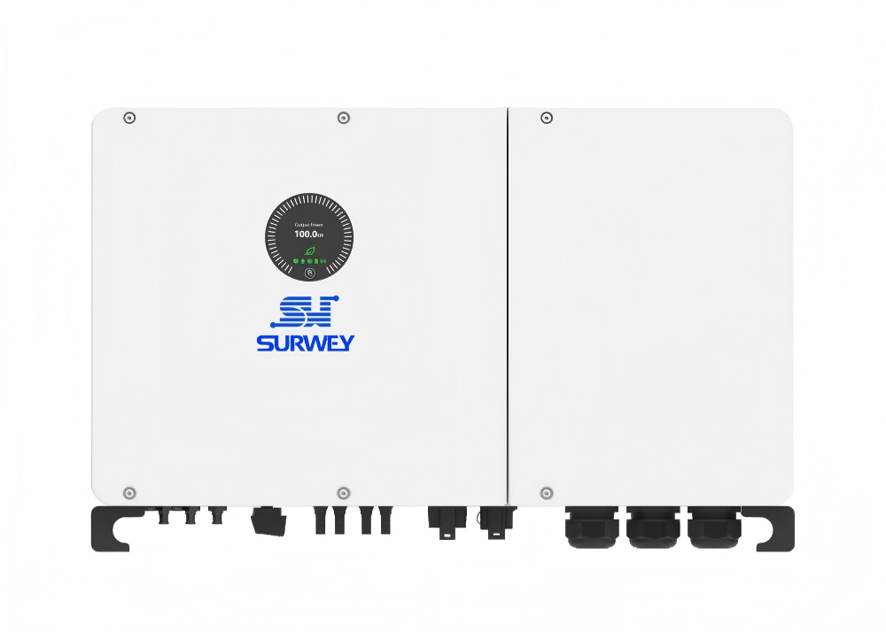
40 kW Three-Phase Grid-Tied Inverter
(3) Selection of the Energy Storage Battery System
This system utilizes an 80 kWh high-voltage rack-mounted lithium iron phosphate (LiFePO₄) energy storage battery system with a modular design. Each module has a capacity of 16 kWh, and five modules are connected in series to achieve a total capacity of 80 kWh. The key technical parameters are as follows:
The battery type is lithium iron phosphate (LiFePO₄). Each module has a standard voltage of 51.2 V and a rated capacity of 100 Ah. The system’s rated voltage is 819.2 V, with an operating voltage range of 672 V to 928 V. The usable energy capacity is 73.73 kWh, offering high energy density and excellent charge/discharge performance;
The system’s rated DC power is 80 kW, with a maximum charge/discharge current of 100 A and a peak discharge current of 125 A (2 minutes, 25°C), capable of meeting the system’s high-power charge and discharge requirements. The cycle life is ≥8,000 cycles (25°C, 0.5C/0.5C, 90% DOD), ensuring an exceptionally long service life;
Operating temperature range: 0°C to 55°C for charging and -20°C to 55°C for discharging, making it suitable for wide-temperature operating environments in commercial and industrial settings; relative humidity: 5% to 85% RH; altitude ≤3,500 m; enclosure protection rating: IP20; suitable for indoor and outdoor rack-mounted installation;
Built-in BMS (Battery Management System) supporting CAN 2.0/RS485 communication, enabling real-time monitoring of individual cell voltage, temperature, and current. It features multiple protection functions, including overcharge, over-discharge, overcurrent, overtemperature, and insulation monitoring. It is also compatible with the communication protocols of mainstream inverters, enabling coordinated control with the inverter to ensure the safe and stable operation of the battery system;
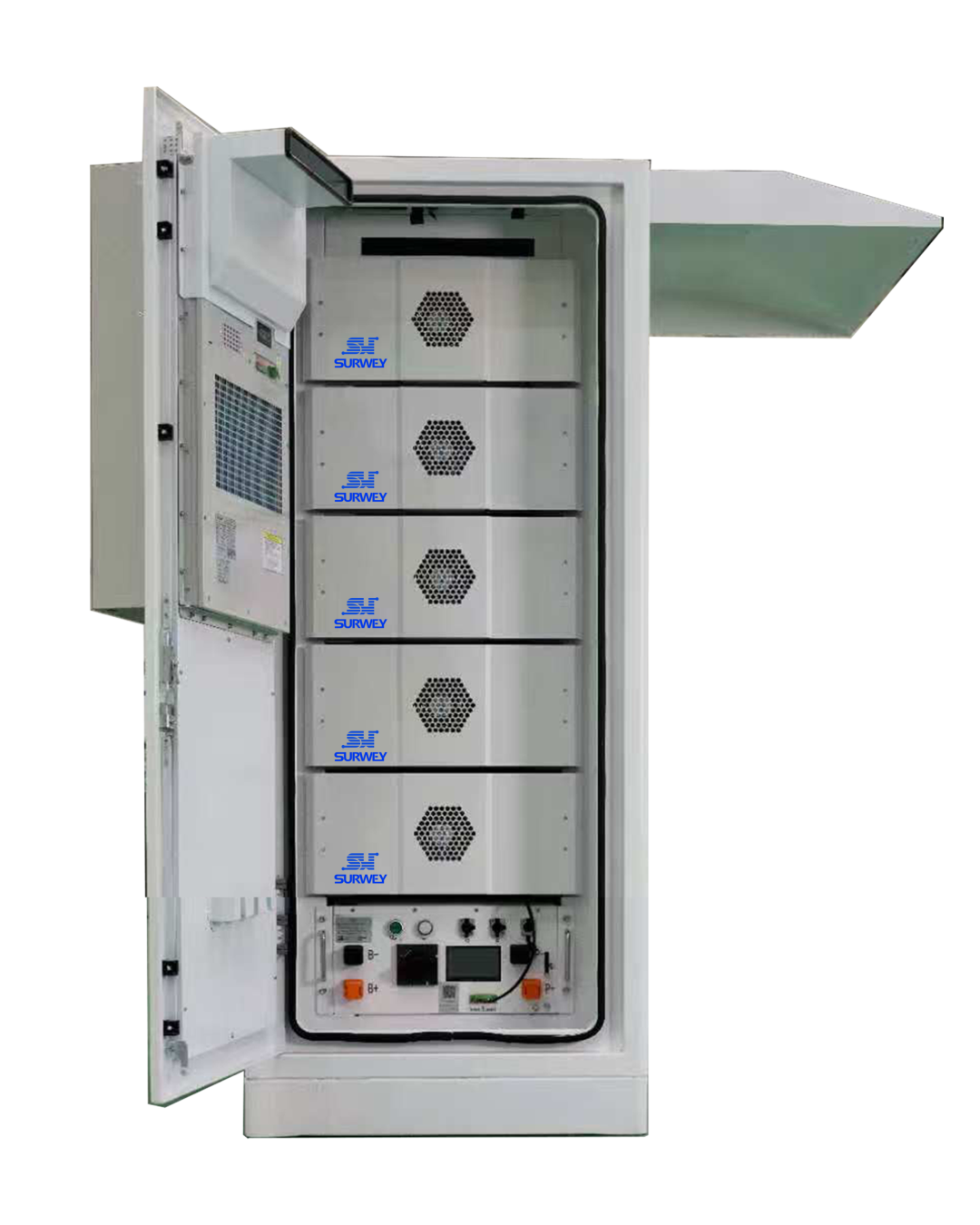
80 kWh High-Voltage Rack-Mounted Lithium Iron Phosphate Energy Storage Battery System
V. System Electrical Design and Compatibility Verification
(1) Verification of Series and Parallel Design for the PV Array
The series and parallel design of the PV array is critical to the system’s stable operation. This system underwent detailed verification of the parameter compatibility between the PV modules and the inverters to ensure that the electrical parameters of each string of PV modules fall entirely within the inverter’s MPPT operating range. The specific verification is as follows:
Single-string voltage calculation: Each string in this system consists of 16 650W photovoltaic modules connected in series. Under standard test conditions (STC, 25°C), the open-circuit voltage of a single module is 49.73V, and the operating voltage is 41.56 V. Therefore, the open-circuit voltage of a single string is 49.73 V × 16 = 795.68 V, and the operating voltage of a single string is 41.56 V × 16 = 664.96 V.
MPPT Range Compatibility Verification: The inverter’s MPPT full-load operating voltage range is 500 V–850 V, and its operating voltage range is 180 V–1,000 V. The operating voltage of a single-string module, 664.96 V, falls within the MPPT full-load operating range, ensuring that the inverter can always track the maximum power point of the PV array under full-load conditions, thereby maximizing PV power generation.
At the same time, considering the voltage temperature coefficient of the modules, under extreme high-temperature conditions (module temperature of 70°C), the open-circuit voltage of a single module drops to 49.73 V × (1 – 0.25%/°C × (70 – 25)) = 44.16 V. resulting in a single-string open-circuit voltage of 44.16 V × 16 = 706.56 V, which remains well above the inverter’s MPPT activation voltage of 195 V and thus falls within the MPPT operating range; Under extreme low-temperature conditions (module temperature -40°C), the open-circuit voltage of a single module rises to 49.73 V × (1 + 0.25%/°C × (25 + 40)) = 57.83 V, resulting in a single-string open-circuit voltage of 57.83 V × 16 = 925.28 V, which is below the inverter’s maximum DC voltage of 1100 V. There is no risk of overvoltage, and this fully meets safety requirements for operation.
Current Compatibility Verification
Under STC conditions, the short-circuit current of a single-string module is 16.56 A, and the operating current is 15.65 A. The inverter’s maximum input current per MPPT channel is 40 A, and the maximum short-circuit current is 50 A. The current of a single string is well below the inverter’s current limits. Additionally, with two strings of modules connected to each MPPT channel, the total input current is approximately 31.3 A, which remains within the inverter’s permissible current range. There is no risk of overcurrent, ensuring the system’s electrical safety.
(2) System Electrical Topology Design
This topology enables multiple energy flow paths:
Prioritizing PV Power for Loads
During the day, PV-generated power is prioritized for on-site loads, with excess electricity stored in the battery system. This enables on-site consumption of PV power and reduces power loss from reverse transmission.
Peak-Valley Tariff Arbitrage
During off-peak hours, the inverter controls the battery system to charge, storing low-cost electricity; during peak-rate periods, the battery system discharges to supply loads in conjunction with PV generation, reducing the amount of electricity purchased from the utility grid during peak hours and significantly lowering electricity costs.
Emergency Backup Power
In the event of a utility grid failure, the system can switch to off-grid operation within 10 ms, with the PV and energy storage systems providing uninterrupted power to critical loads, ensuring the continuity of commercial and industrial operations.
Peak Shaving and Valley Filling
Based on the user’s electricity load curve, the system intelligently adjusts charging and discharging strategies—discharging during peak hours and charging during off-peak hours—to achieve peak shaving and valley filling. This reduces the user’s demand-based electricity charges while enhancing grid stability.
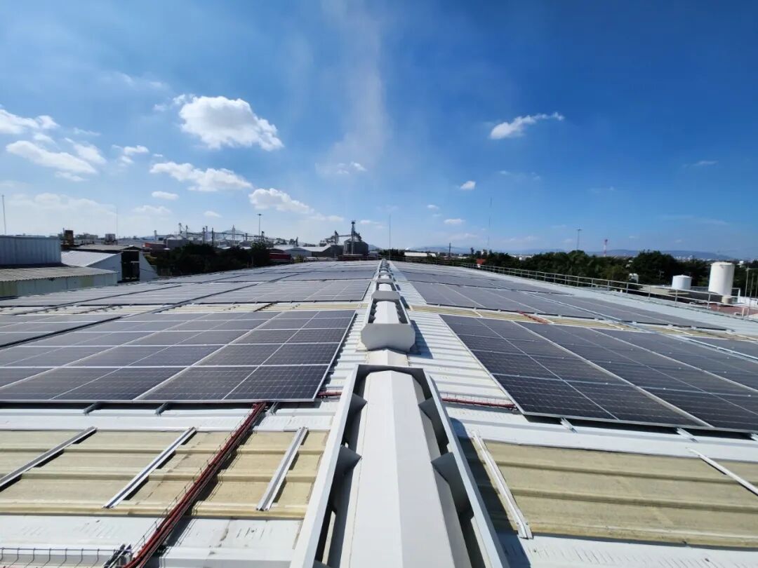
40 kW / 80 kWh Commercial and Industrial Solar Power and Energy Storage System
VI. System Functions and Operating Modes
Grid-Connected Self-Consumption Mode
This is the system’s default operating mode. During the day, solar power is prioritized to supply local loads, and excess electricity is stored in the energy storage batteries. When solar power generation is insufficient, the energy storage batteries supplement the power supply, thereby maximizing the utilization of solar power and minimizing the amount of electricity purchased from the utility grid.
Peak-Valley Arbitrage Mode
The system incorporates built-in peak-valley electricity pricing strategies. Based on local electricity pricing policies, it automatically charges the battery during off-peak hours and discharges the battery to supply loads during peak hours. This enables charging during low-cost periods and discharging during high-cost periods, significantly reducing electricity costs and enhancing the system’s economic efficiency.
Off-Grid Emergency Mode
In the event of a power outage or grid failure, the system can quickly switch to off-grid operation mode. The PV and energy storage systems then provide stable AC power to critical loads, ensuring uninterrupted power supply to production equipment, office equipment, and other essential loads. Additionally, the system supports black start functionality, enabling it to automatically start up in the absence of grid power and quickly restore off-grid system operation.
Peak Shaving and Valley Filling Mode
Based on the user’s historical electricity load data, the system automatically generates an optimal charging and discharging strategy. It discharges during peak electricity consumption periods to reduce grid peak power and lower demand charges; it charges during off-peak periods to smooth out grid loads. Additionally, it can respond to grid demand response commands to generate additional revenue.
Smart Monitoring and O&M Mode
The system is equipped with a smart monitoring platform that collects real-time operational data from PV modules, inverters, and battery systems—including power generation, charge/discharge levels, operational status, and fault information. Users can remotely monitor system performance via a mobile app or computer. Additionally, the system features automatic fault early warning capabilities to promptly detect and address system malfunctions, thereby reducing O&M costs and enhancing operational reliability.
VII. System Security and Protection Design
Device-Level Safety Protection
All core devices are equipped with comprehensive built-in safety protection features. The photovoltaic modules are encased in double-glazed glass, providing excellent insulation and fire resistance; the inverters feature multiple protection functions, including DC reverse connection protection, overvoltage and overcurrent protection, short-circuit protection, insulation monitoring, and anti-islanding protection. They also incorporate built-in Class C surge arresters to effectively withstand lightning overvoltages; The energy storage battery system features a built-in Battery Management System (BMS) that enables real-time monitoring of cell voltage and temperature. It includes multiple protection functions such as overcharge, over-discharge, overcurrent, overtemperature, and insulation monitoring. Additionally, the system utilizes a lithium iron phosphate (LiFePO₄) battery chemistry, which offers excellent thermal stability and eliminates the risk of thermal runaway.
System-Level Safety Protection
The system’s DC side uses specialized PV cables with weather resistance, abrasion resistance, and flame-retardant properties. DC circuit breakers and fuses are installed to enable rapid disconnection in the event of a fault. On the AC side, a grid-connection cabinet is installed, featuring built-in AC circuit breakers, surge protectors, and power quality monitoring devices to provide overcurrent, short-circuit, and lightning protection on the AC side, while ensuring that the power quality of the grid-connected electricity meets grid requirements; The system is equipped with a comprehensive grounding system; all equipment enclosures are reliably grounded, effectively reducing the risk of electric shock while enhancing lightning protection.
Installation-Level Safety Measures
System installation strictly adheres to relevant code requirements. PV mounting structures are made of hot-dip galvanized steel, offering excellent corrosion resistance and structural strength to withstand extreme weather conditions; Cables are routed through conduits or cable trays to prevent wear and exposure to direct sunlight, and are treated to provide protection against water, fire, and rodent damage; Upon completion of installation, rigorous insulation testing, ground resistance testing, and pre-grid-connection testing are conducted to ensure the system complies with safety standards and eliminate potential safety hazards.
VIII. Installation and Construction Plan
Preliminary Preparation Phase
Conduct a site survey to confirm the load-bearing capacity, orientation, and shading conditions of the installation site, as well as grid connection requirements. Develop a detailed construction plan and safety contingency plan, complete the necessary grid connection procedures and obtain construction permits, and prepare the equipment, materials, and tools required for construction.
Foundation Construction Phase
In accordance with the design plan, construct the foundations for the PV mounting structures, inverters, and battery cabinets, ensuring that the structural strength and levelness of the foundations meet design requirements. Simultaneously, complete the installation of the grounding system to ensure that the grounding resistance complies with regulatory standards.
Equipment Installation Phase
Install and commission the PV mounting structures, ensuring their levelness and angles meet design requirements. Then install and secure the PV modules, ensuring they are firmly mounted with uniform spacing. Simultaneously, install and secure the inverters, battery cabinets, and grid-connection cabinets, ensuring the equipment is installed stably with adequate ventilation and heat dissipation.
Electrical Wiring Phase
Perform series and parallel wiring of the photovoltaic modules, as well as the installation and connection of DC cables, ensuring that cable connections are secure, polarity is correct, and proper waterproofing and insulation are in place; then connect the inverters to the battery cabinets and grid-connection cabinets, install and connect AC cables, ensuring wiring complies with standards, phase sequence is correct, and cables are properly protected.
Commissioning and Grid Connection Phase
After completing the electrical wiring, perform system insulation tests, ground resistance tests, open-circuit voltage tests, and short-circuit current tests to ensure the system’s electrical performance meets requirements; then commission the inverter, configure system operating parameters, and integrate the monitoring platform; finally, conduct pre-grid-connection acceptance testing, apply for grid connection with the utility, and complete the grid connection acceptance process.
Acceptance and Handover Phase
Once the system is operational and functioning normally after grid connection, a comprehensive system acceptance inspection is conducted, covering equipment installation quality, electrical performance, power generation performance, and safety measures. Upon successful acceptance, the system is handed over to the user, along with operational training, operation and maintenance manuals, and warranty services to ensure the user can operate the system properly.
IX. System Benefit Analysis
Direct Electricity Cost Savings
The system generates an average of approximately 208 kWh per day, with an annual generation of approximately 75,000 kWh. This directly replaces electricity purchased from the grid. At the same time, by taking advantage of peak-off-peak electricity pricing, it can further reduce electricity costs. Based on the commercial and industrial electricity rate of 0.8 yuan / kWh, annual electricity cost savings amount to approximately 60,000 yuan. Furthermore, with a service life of over 25 years, the system delivers significant long-term economic benefits.
Reduction in Demand Charges
Through its peak-shaving and valley-filling capabilities, the system effectively reduces the user’s peak power consumption, thereby lowering demand charges. It also mitigates the risk of rate surges caused by grid peak loads, further reducing electricity costs.
Value as a Backup Power Source
The system features off-grid emergency power supply capabilities, providing uninterrupted power to critical loads during utility power outages. This prevents production losses and operational risks caused by power outages, ensuring the continuity of production and operations. For industrial and commercial users with high requirements for power supply reliability, it offers exceptional value as a backup power source.
Reduced O&M Costs
The system’s core equipment comes with extended warranty coverage and is integrated with a smart monitoring platform that enables automatic fault alerts and remote operation and maintenance. This reduces labor and time costs associated with on-site maintenance, ensuring the system’s long-term stable operation.
X. Conclusion and Warranty Services


