
Technical Proposal for a 15 kW Three-Phase Grid-Connected Photovoltaic Energy Storage System in Malaysia
I. Project Overview
Operating Principles of a 15-kW Three-Phase Grid-Tied Photovoltaic Energy Storage System
To meet the dual requirements of on-site power reliability and cost-effectiveness, this system adopts a hybrid photovoltaic-storage grid operation architecture that integrates grid-connected power generation, energy storage for peak shaving, off-grid backup, and smart load management. It enables on-site consumption of self-generated photovoltaic power, storage of surplus electricity, supplementation during power shortages, and seamless switching during grid anomalies. This completely resolves issues such as equipment downtime and production interruptions caused by grid disturbances and short-term power outages, while maximizing the utilization of clean photovoltaic energy and reducing electricity costs for industrial and commercial users.
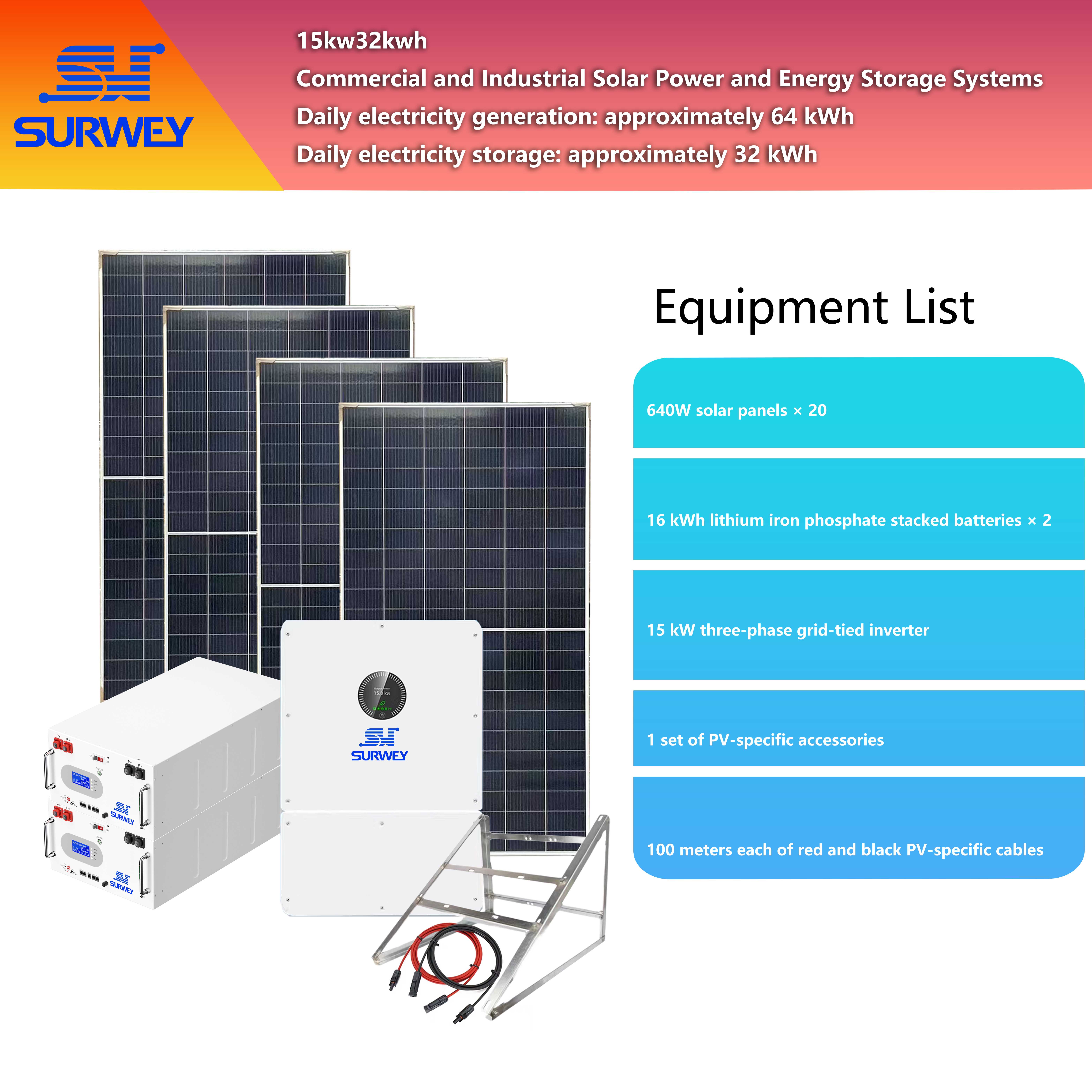
Configuration Diagram for a 15 kW Three-Phase Grid-Tied Photovoltaic Energy Storage System
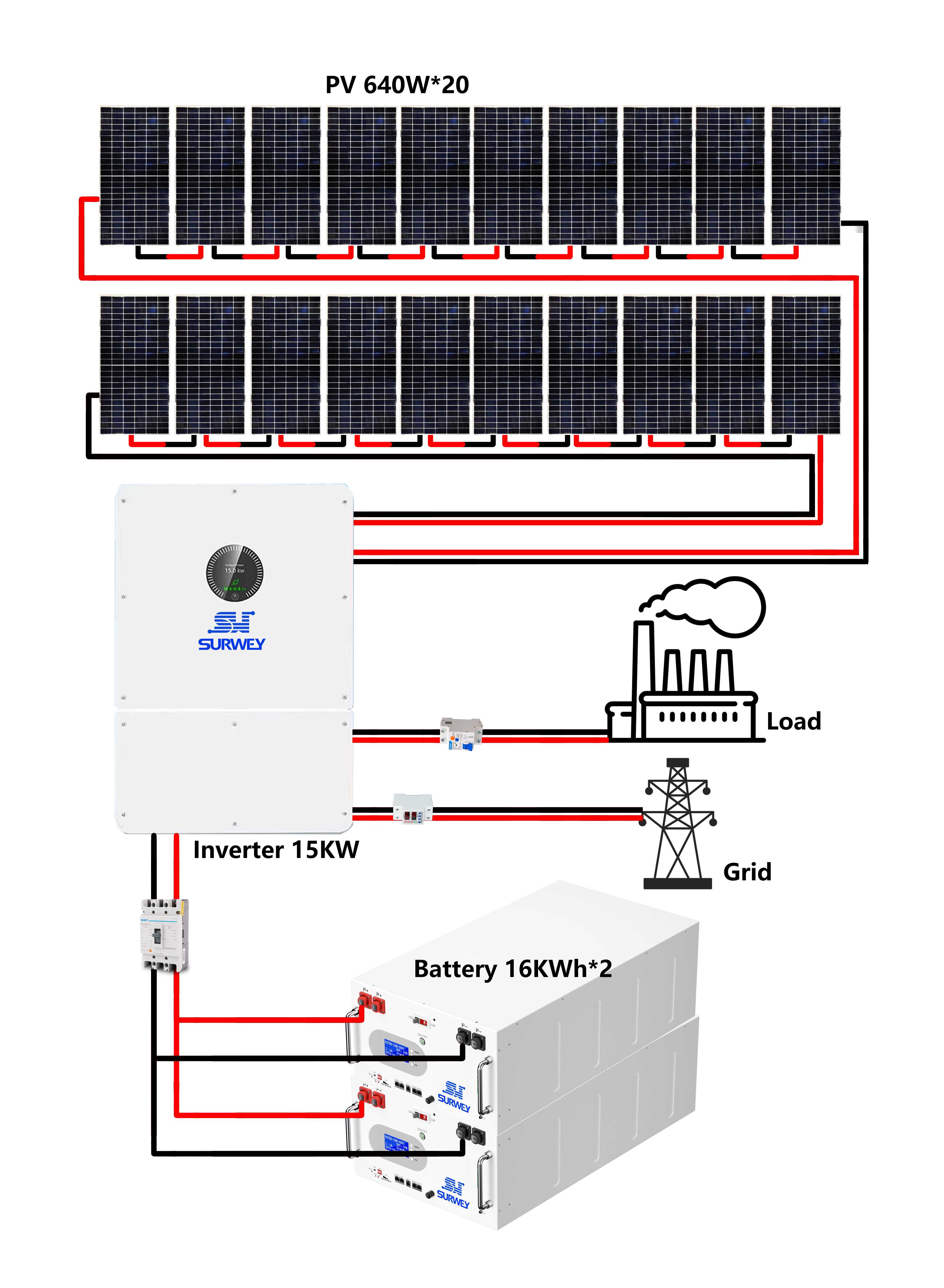
Topology Diagram of a 15 kW Three-Phase Grid-Tied Photovoltaic Energy Storage System
II. On-Site Load Analysis and Design Basis
| Equipment Name | Single-unit power | Quantity | Total Power | Power Supply Standard |
|---|---|---|---|---|
| Dissolved Air Pump |
1.5kW |
1 unit |
1.5kW |
415 V, three-phase |
| Slag Scraper |
0.25kW |
1 unit |
0.25kW |
415 V, three-phase |
| Blower |
1.5kW |
1 unit |
1.5kW |
415 V, three-phase |
| Agitation Motor for a Chemical Dosing Machine |
0.55kW |
3 unit |
1.65kW |
415 V, three-phase |
| Dosing Pump |
90W |
3 unit |
0.27kW |
415 V, three-phase |
| Inlet Boost Pump |
1.5kW |
1 unit |
1.5kW |
415 V, three-phase |
|
UV Sterilization Unit |
160W |
1 unit |
0.16kW |
415 V, three-phase |
| Total |
— |
— |
Approximately 6.83 kW |
According to statistics, the total rated power of the on-site loads is 6.83 kW. Taking into account the inrush current characteristics of industrial motor loads and the simultaneous operation factor for multiple devices, the system’s peak operating power is approximately 8–10 kW. This project is equipped with a 15 kW three-phase grid-tied inverter, which provides ample power redundancy. The equipment is capable of withstanding a short-term overload of 200% of its rated power for 10 seconds, fully covering the inrush current of inductive loads such as pumps and mixer motors. This prevents overload tripping and shutdown failures, ensuring the system’s stability under load.
On-site production equipment operates continuously 24 hours a day. During daytime hours when PV generation is high, the load-power match is excellent, enabling the local consumption of PV electricity. At night, when there is no PV output, the energy storage system provides power as the primary source, with the utility grid stepping in to supplement any power shortfall. This establishes a tiered power supply logic of “PV first, energy storage for peak shaving, and the utility grid as a backup,” maximizing the utilization of clean energy and reducing peak-hour electricity costs.
The overall design of this system strictly adheres to four core principles: reliability, adaptability, cost-effectiveness, and scalability. It ensures stable, round-the-clock operation through industrial-grade equipment standards; is adapted to Malaysia’s tropical climate characterized by high temperatures, high humidity, and strong convection; optimizes hardware and software configurations based on local solar irradiance parameters and electricity pricing structures; and includes provisions for equipment parallel connection and capacity expansion to accommodate future load upgrades. The solution is fully compliant and highly adaptable.
III. Overall System Architecture and Operating Mode
This system employs a DC-coupled photovoltaic-storage hybrid grid topology and consists of five core modules: a photovoltaic power generation unit, a bidirectional inverter control unit, a lithium iron phosphate energy storage unit, an AC power distribution unit, and a smart energy monitoring unit. Each module operates in coordination with the others while remaining independently controllable. The DC output from the PV array is directly connected to the MPPT DC input of the inverter, while the energy storage battery bank is directly connected to the inverter via a DC bus. The AC side is simultaneously connected to the utility grid and on-site terminal loads, enabling coordinated power supply from multiple energy sources.
In grid-connected operation mode, the system employs an intelligent energy dispatch strategy that prioritizes allocating photovoltaic power to meet local load demand, with surplus energy automatically stored in the battery bank. Once the energy storage system is fully charged, the system can be configured—based on O&M requirements—to either feed surplus power back into the grid or operate in zero-reverse-flow mode; When the PV output is insufficient to meet load demand, the energy storage system instantly supplements the power, with the utility grid ultimately providing backup power. The entire process is managed through automated, intelligent dispatch without the need for manual intervention, maximizing energy utilization.
The system features millisecond-level seamless switching between grid-connected and off-grid modes. In the event of utility grid failures—such as power outages, overvoltage, undervoltage, or frequency abnormalities—the inverter can switch from grid-connected to off-grid mode within 10 ms. The PV array and energy storage system then jointly provide independent power to the load. The switching process involves no power interruption, no voltage drop, and no downtime, making it fully compatible with continuous industrial production conditions. Once grid parameters return to normal, the system automatically and smoothly switches back to grid-connected operation, operating adaptively throughout the process with exceptional stability.
The equipment integrates a dedicated generator connection port and intelligent hierarchical load control logic, enabling it to work in conjunction with a diesel generator as a backup to address extreme conditions such as prolonged rainy weather or depleted energy storage; simultaneously, it can automatically engage or disengage non-core loads based on battery SOC status and load priority, prioritizing continuous power supply to critical production equipment, thereby comprehensively enhancing the system’s power supply redundancy and fault tolerance.
Core system technical parameters: PV installed capacity of 12.8 kW, inverter rated output power of 15 kW, total energy storage system capacity of 32 kWh, system rated AC voltage of 230 V/400 V three-phase configuration, compatible with the local 415 V industrial voltage range; Average daily PV power generation under standard operating conditions is 64 kWh; the inverter’s MPPT voltage operating range is 150 V to 850 V; all operating parameters are precisely matched, and the system’s hardware and software configuration has been verified through simulation to ensure optimal operational efficiency.
IV. Design of the Photovoltaic Subsystem
4.1 Module Selection
4.2 Array Design and Voltage Matching
Electrical parameter verification: The short-circuit current of a single string of modules is approximately 14 A. When two strings are connected in parallel, the total input current is ≤30 A, which is below the inverter’s single-channel MPPT maximum input current limit of 40 A. This provides ample current headroom, effectively mitigating the risks of overload and overheating. Connecting dual-string arrays to the same MPPT channel simplifies wiring and minimizes losses, while also reducing the difficulty of troubleshooting during later operation and maintenance, thereby balancing system reliability and maintainability.
4.3 Power Generation Estimation
Based on on-site electricity load calculations, photovoltaic power generation can cover more than 35% of the site’s average daily electricity consumption. Combined with the peak-shaving and valley-filling capabilities of the energy storage system, this can further increase the self-generation and self-consumption rate, thereby maximizing reductions in electricity costs during peak-rate periods. The project’s photovoltaic array is installed at an optimal tilt angle of 10°–15°, adapted to the local latitude and sunlight angle, to maximize annual sunlight reception efficiency and ensure stable power generation.
V. Design of the Energy Storage Subsystem
5.1 Battery Selection and Configuration
A single 16 kWh battery pack has a nominal voltage of 51.2 V, a standard charge/discharge current of 150 A, and a peak discharge current of 300 A. When two units are connected in parallel, the system’s maximum charge/discharge current reaches 300 A, precisely matching the 290 A maximum charge/discharge current of the 15 kW three-phase grid-tied inverter. This eliminates power redundancy and waste, as well as any parameter incompatibility issues. The battery’s operating voltage range is 43.2 V to 58 V, which fully aligns with the inverter’s 40 V to 60 V battery operating voltage range. This eliminates the need for additional voltage conversion equipment, reduces intermediate losses, and improves the system’s overall conversion efficiency.
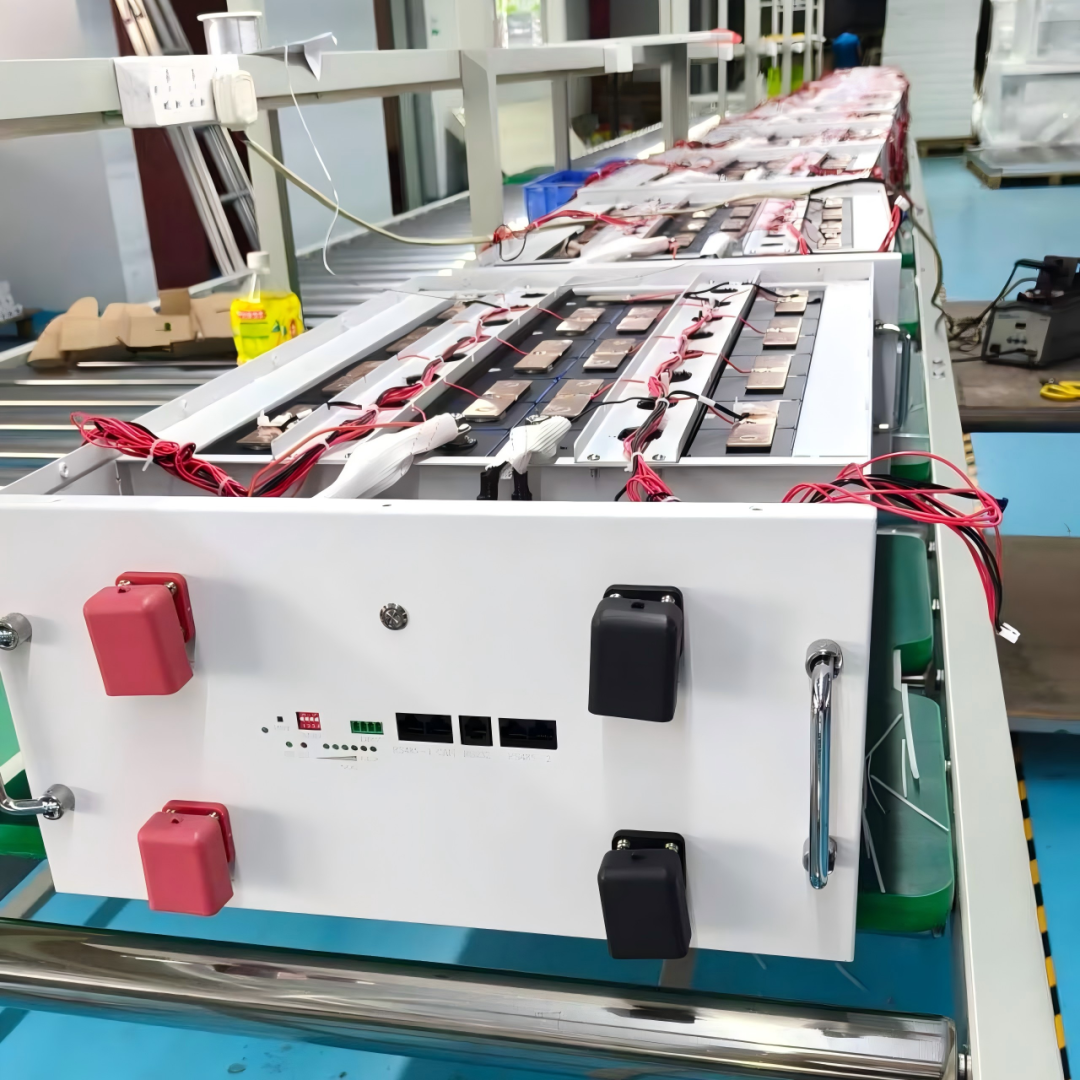
SW-T512V16KWH-L2 Stackable Lithium-Ion Energy Storage Battery
5.2 BMS and Communication
The battery supports multi-mode communication via CAN 2.0, RS485, and Bluetooth, and natively supports the communication protocol of 15 kW three-phase grid-tied inverters, enabling data exchange and coordinated control between the inverter and the energy storage system. The inverter can accurately read the energy storage system’s real-time status and dynamically match charging and discharging power to achieve precise energy scheduling; the accompanying smart app enables remote monitoring of system operating parameters, alarm information, and energy consumption data, facilitating unattended, intelligent operation and maintenance.
5.3 Capacity and Runtime Analysis
In grid-connected mode, the battery primarily serves to smooth out peak and off-peak loads and acts as a backup power source. It charges during the day using surplus solar power and discharges during evening peak hours, thereby saving on peak-hour electricity costs and avoiding curtailed generation. During short-term power outages, it seamlessly takes over the load while waiting for the grid to recover or for the generator to start.
The energy storage batteries use industrial-grade lithium iron phosphate (LiFePO₄) cells with a cycle life of ≥8,000 cycles under standard conditions. With an average of 0.5 cycles per day, the system’s effective service life can exceed 15 years. The system supports parallel connection of up to 16 battery units for capacity expansion, with a maximum expandable energy storage capacity of 256 kWh. No replacement of inverter equipment is required later on; capacity upgrades can be achieved simply by adding new battery packs. The system offers exceptional scalability and compatibility, meeting enterprises’ future load expansion needs.
VI. Design of the Inverter Control Subsystem
6.1 Core Characteristics of the 15 kW Three-Phase Grid-Tied Inverter
The unit supports 100% three-phase unbalanced load operation, with each phase capable of independently handling 50% of the rated power, making it perfectly suited for industrial environments with unbalanced three-phase loads. It also features a short-term overload capacity of 200% of the rated power for 10 seconds, effectively withstanding the inrush current from inductive loads such as motors during startup. This prevents shutdowns due to transient overloads and equipment error messages, significantly enhancing operational stability under complex conditions.
6.2 Grid-Tied/Off-Grid Switching and Backup Power
The unit integrates a dedicated diesel generator coupling interface, supporting coordinated dispatch of multiple energy sources—including diesel generators, solar power, energy storage, and the utility grid. Under extreme conditions such as total lack of sunlight or grid failures, it can automatically activate the generator to supplement power supply, establishing a multi-layered power supply redundancy system. An built-in intelligent load prioritization and control algorithm automatically connects or disconnects non-core loads based on battery SOC, grid status, and load priority, ensuring continuous power supply to critical production loads.
6.3 Parallel Expansion and Protection
The unit comes standard with a high-definition OLED display panel and physical control buttons. It supports bidirectional RS485 and USB communication and, when paired with a dedicated Wi-Fi monitoring module, enables remote cloud-based data monitoring, parameter tuning, report export, and fault alerts, ensuring convenient and efficient intelligent operation and maintenance. Built to industrial-grade standards and backed by a 10-year manufacturer’s warranty, the unit offers full assurance of long-term operational reliability and stability.
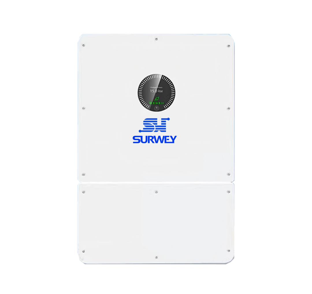
15 kW Three-Phase Grid-Tied Inverter
VII. System Electrical and Safety Design
The energy storage DC circuit uses 25-square high-current battery-grade cables, with a current-carrying capacity matched to the system’s maximum charge and discharge currents, thereby eliminating issues such as cable overheating and voltage drop losses. The battery parallel circuit is equipped with dual overload protection—DC circuit breakers and fuses—which, combined with the BMS system’s multi-level electrical protection, forms a dual-safety system of “built-in equipment protection + external component protection,” comprehensively ensuring the operational safety of the energy storage circuit.
The system’s AC side employs a zoned power distribution design, with separate circuits for grid connection and load supply. It is equipped with a full suite of power distribution components—including grid-connection switches, ground-fault circuit interrupters (GFCIs), surge protectors, and overload protectors—ensuring that maintenance and operations do not interfere with one another. The inverters feature built-in Type II/III AC/DC composite lightning surge protection, which, when combined with the facility’s external lightning protection system, effectively withstands lightning strikes and grid transient overvoltage disturbances, meeting industrial electrical safety standards.
The system integrates comprehensive electrical safety protection features, including PV reverse polarity protection, DC switch isolation, insulation resistance monitoring, residual current monitoring, AC short-circuit protection, ground fault monitoring, grid undervoltage protection, islanding protection, and optional AFCI arc fault protection, providing all-around coverage against various electrical fault risks.
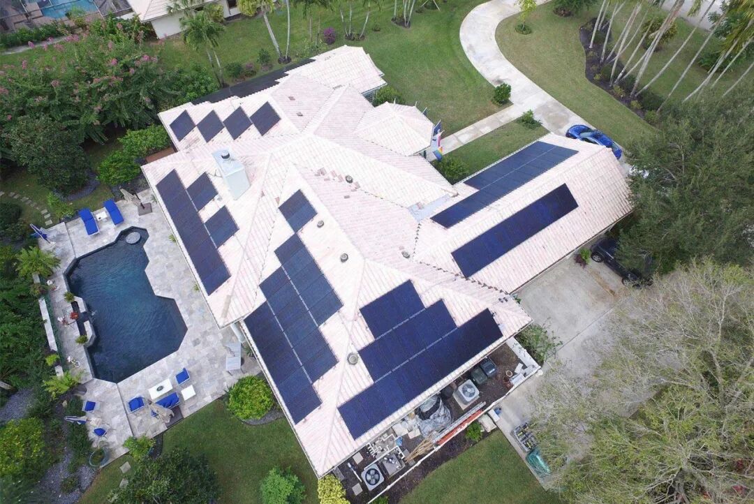
Malaysia: Photovoltaic Energy Storage Systems for Villas
VIII. Installation, Construction, and O&M Guidelines
Equipment installation follows specialized compatibility principles. Inverters are installed in well-ventilated, shaded outdoor locations to prevent performance degradation caused by temperature rise due to direct sunlight; energy storage batteries are installed in a rack-mounted, organized configuration, with the operating environment maintained within the optimal range of 15–35°C to ensure stable operation of the energy storage system and minimize environmental degradation.
Construction strictly separates AC and DC circuits as well as high- and low-voltage lines, with isolated routing to prevent electromagnetic interference. All outdoor connection points are treated with waterproof, insulated, and corrosion-resistant sealing, and the entire system’s metal structure is reliably grounded in accordance with industrial electrical safety standards, eliminating risks of electrical leakage and static electricity.
The system employs a standardized commissioning process featuring staged power-up and item-by-item verification. This begins with circuit continuity and insulation testing, followed sequentially by DC power-up, battery communication pairing, grid-connected/off-grid switching, and full-load testing. After verifying that the system’s energy dispatch, protection functions, and power supply accuracy meet standards, grid connection and handover are completed, along with specialized training on operation and maintenance.
The system features intelligent self-diagnostic and remote monitoring capabilities, enabling unattended operation. Routine maintenance requires only periodic basic inspections, such as panel cleaning, terminal tightening, equipment condition checks, and log reviews; minor faults can be remotely diagnosed and resolved. It is recommended to conduct a comprehensive system inspection every six months to ensure long-term, efficient, and stable operation of the equipment, resulting in low overall O&M costs and high reliability.
IX. System Benefits and Summary
In terms of power supply reliability, addressing the issues of grid fluctuations and frequent short-term power outages in Malaysian industrial zones, this 15 kW hybrid grid-connected PV-storage system, leveraging 10 ms seamless switching technology and 32 kWh of emergency energy storage capacity, establishes a multi-redundant power supply system integrating the utility grid, PV, and energy storage. It completely mitigates the risks of production interruptions, equipment damage, and loss of production capacity caused by power outages and voltage disturbances, ensuring the continuity and stability of industrial production while reducing the enterprise’s production and operational risks.
In summary, this 15 kW three-phase grid-connected PV-storage system in Malaysia was custom-designed to accommodate the project site’s sunlight conditions, industrial load characteristics, grid conditions, and climatic environment. The combination of 640 W high-efficiency PV modules, 32 kWh modular energy storage, and a 15 kW professional grid-connected inverter features precise parameter matching, rigorous operational logic, comprehensive safety protections, and ample capacity for future expansion.


