
Technical Solution for a 55 kW/128 kWh U.S.-Standard Grid-Connected Solar-Storage System in Mexico
I. Project Background and Site Conditions
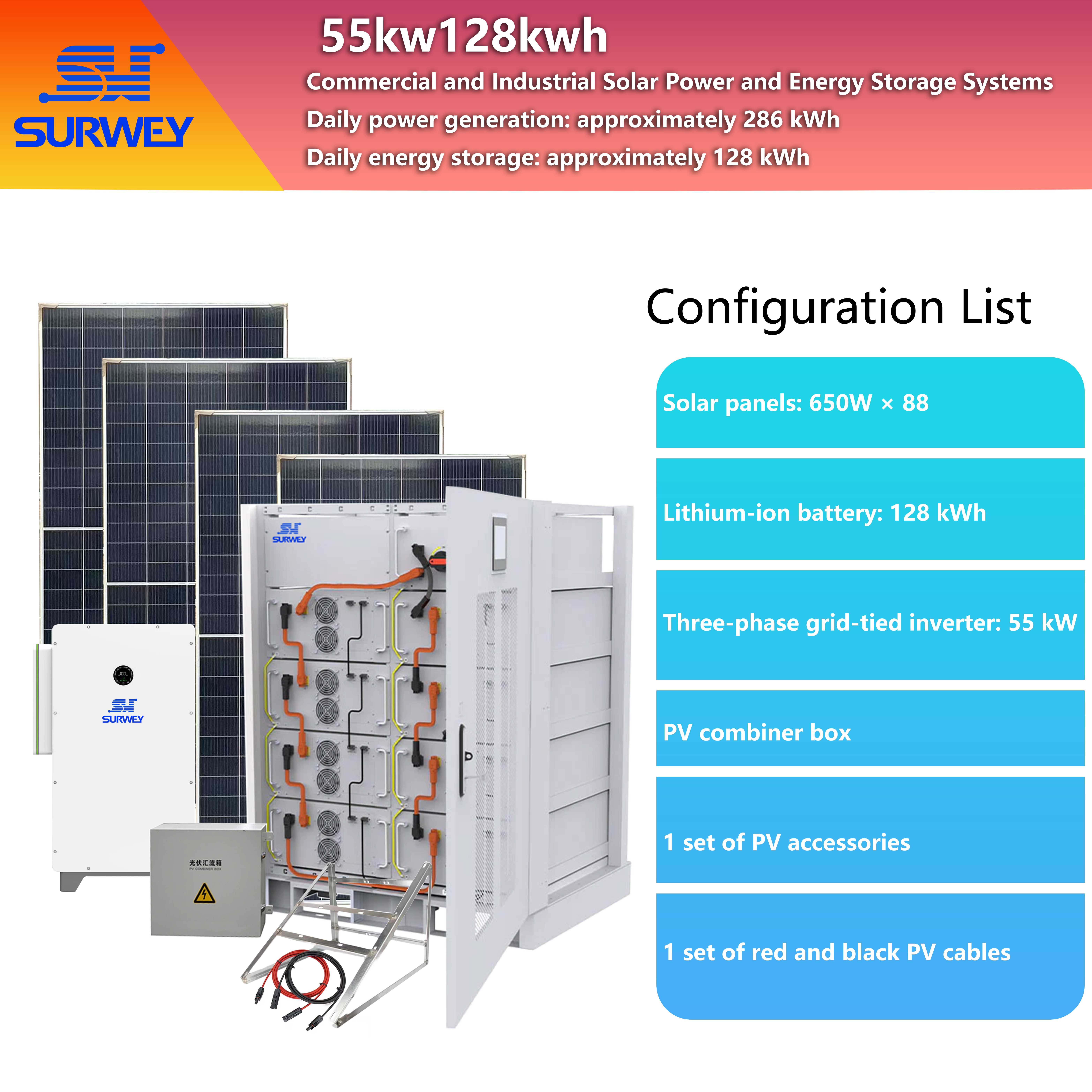
Configuration Diagram for a 55 kW/128 kWh U.S. Standard Hybrid Grid-Connected Solar-Storage System
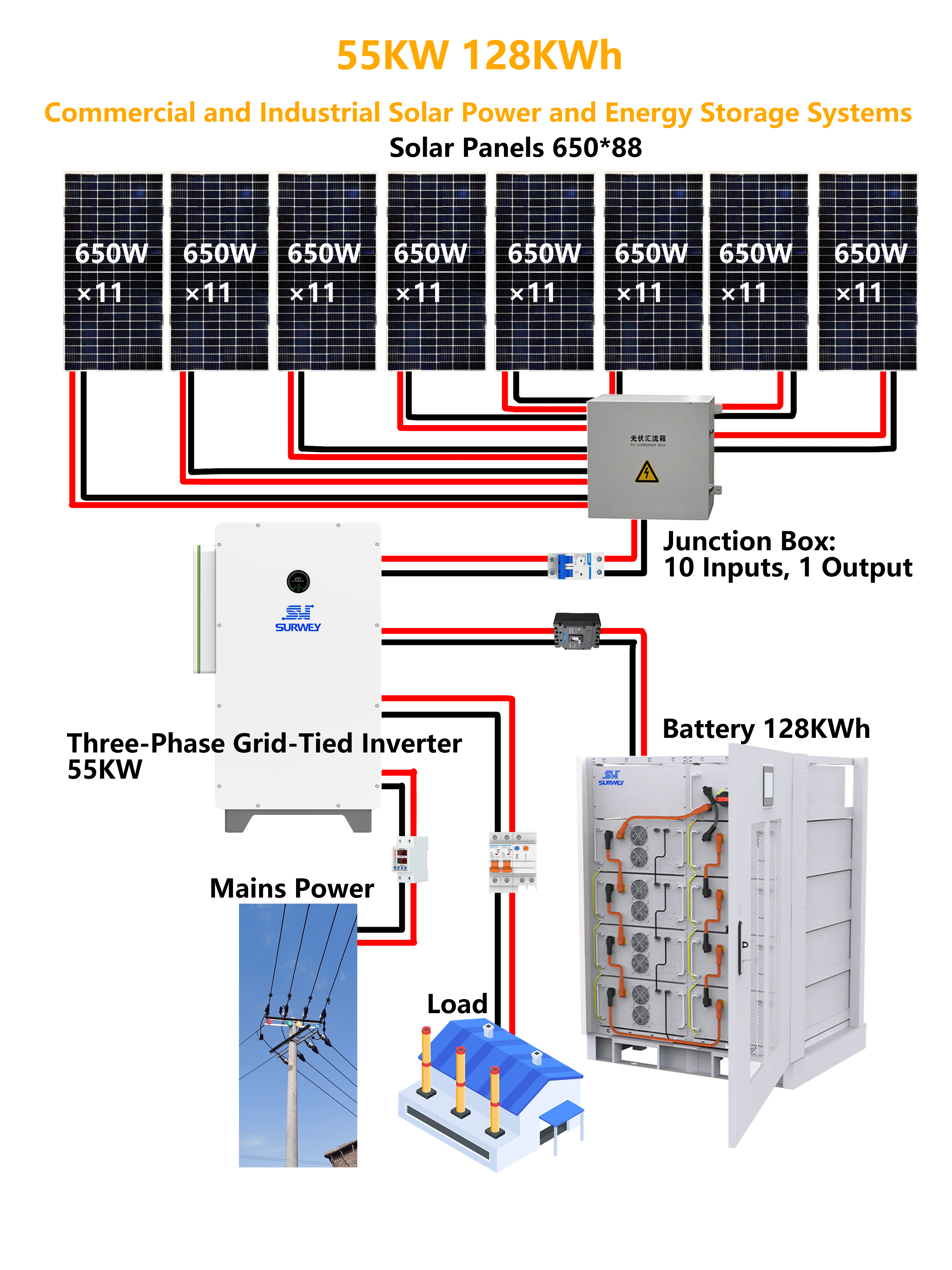
Topology Diagram of a 55 kW/128 kWh U.S. Standard Hybrid Grid-Connected Solar-Storage System
II. Overall System Architecture
This solution employs a three-phase grid-tied photovoltaic-storage integrated architecture. The core equipment includes a photovoltaic module array, a grid-tied inverter, a high-voltage lithium iron phosphate battery bank, a DC combiner box, an AC power distribution system, and a monitoring system. The system has a rated power of 55 kilowatts and a nominal energy storage capacity of 128.6 kilowatt-hours.
The system operates in two modes: grid-connected and off-grid. Under normal grid-connected conditions, the PV system prioritizes power supply to the load; excess electricity is stored in the battery, and any remaining power is fed into the grid once the battery is fully charged. In the event of a grid outage, the inverter switches to off-grid backup mode within 16.6 milliseconds, with the battery and PV system jointly supplying power to critical loads. Once the grid is restored, the system automatically switches back to grid-connected mode; this transition is virtually imperceptible to users.
In terms of capacity ratio, the 57.2-kilowatt PV installation paired with a 55-kilowatt inverter creates a DC over-ratio of approximately 1.04:1. Combined with the energy storage system’s power regulation capabilities, this configuration fully utilizes power generation capacity during periods of high solar irradiance at midday. The 128-kilowatt-hour usable energy storage capacity is roughly equivalent to half a day’s electricity consumption, capable of covering evening peak demand while also providing reliable backup during extreme weather or prolonged grid outages.
The solution places special emphasis on ease of expansion. The inverter’s DC side features a total of 10 PV input channels; currently, only 8 are in use, with 2 interfaces reserved for future use. The AC side supports parallel operation of multiple inverters to scale the system up to 165 kilowatts. The energy storage system also features a modular design that allows for incremental expansion. Should the owner need to increase the load or raise the proportion of self-generation and self-consumption in the future, upgrades can be completed without replacing core equipment.
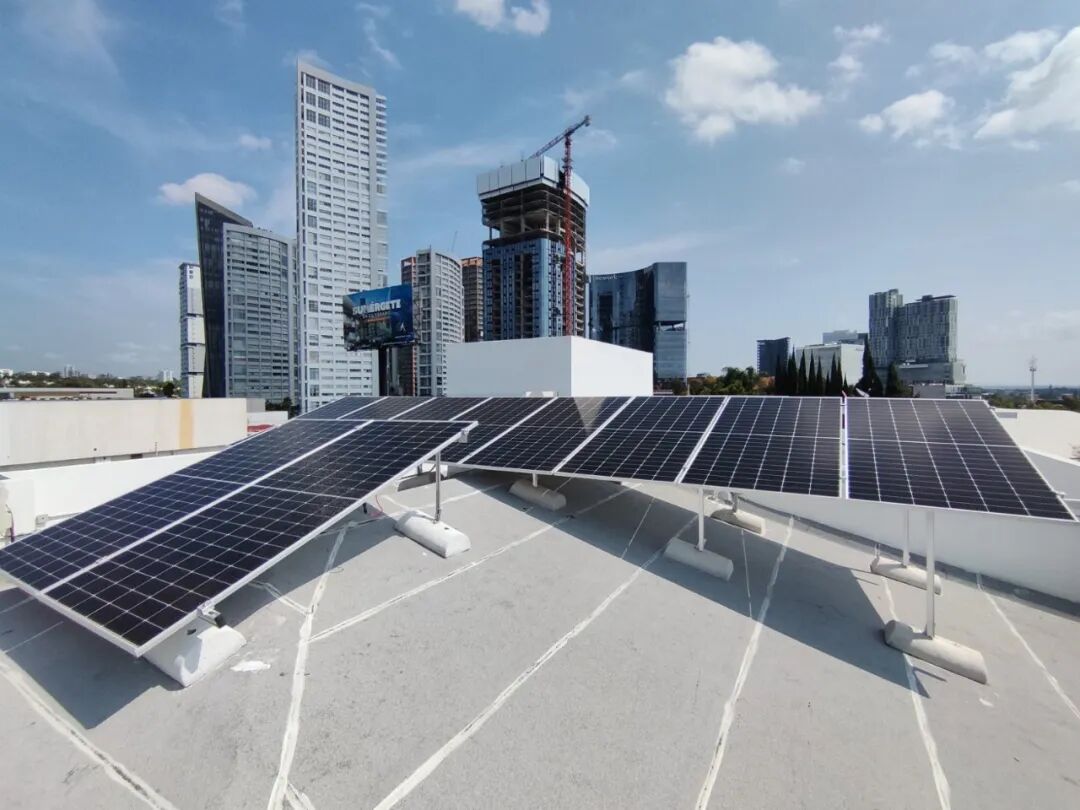
55 kW/128 kWh U.S.-Standard Grid-Connected Solar-Storage System in Mexico
III. Design of Photovoltaic Power Generation Systems
3.1 Component Selection
3.2 Series-Parallel Design and Voltage Matching Verification
3.3 Bracket and Busbar Design
IV. Design of the Energy Storage Subsystem
4.1 Battery Pack Selection and Specifications
The energy storage system uses the SW-G8-128KWH high-voltage rack-mounted lithium iron phosphate battery pack. It consists of eight standard battery modules connected in series, with a nominal system voltage of 512 volts, a nominal capacity of 128.6 kilowatt-hours, a continuous charge/discharge power of 70 to 80 kilowatts, and a peak discharge current of 350 amps (for 2 minutes).
Under conditions of 25°C, 0.5C charge/discharge, and a 90% depth of discharge, this battery pack has a cycle life of no less than 6,000 cycles. Calculated at an average of one cycle per day, its theoretical service life can reach over 15 years, which is essentially aligned with the lifecycle of the photovoltaic system.
The battery features a built-in BMS (Battery Management System) that supports dual communication interfaces—CAN 2.0 and RS-485—enabling seamless integration with the inverter and real-time reporting of parameters such as cell voltage, temperature, SOC, and SOH. The BMS provides multiple protection mechanisms—including overcharge, over-discharge, overcurrent, overtemperature, and short-circuit protection—as well as active balancing functions to ensure the consistency and service life of the entire battery pack.
The battery system’s operating voltage range is 420 V to 580 V, which is highly compatible with the inverter’s battery-side range of 380 V to 650 V; the recommended operating point of 512 V falls precisely within the inverter’s optimal efficiency range. Regarding charge and discharge currents, the inverter supports a maximum of 156 A, while the battery is rated at 100 A (recommended) and 150 A (maximum). The power ratings are well-matched, eliminating any current-limiting bottlenecks on the battery side.
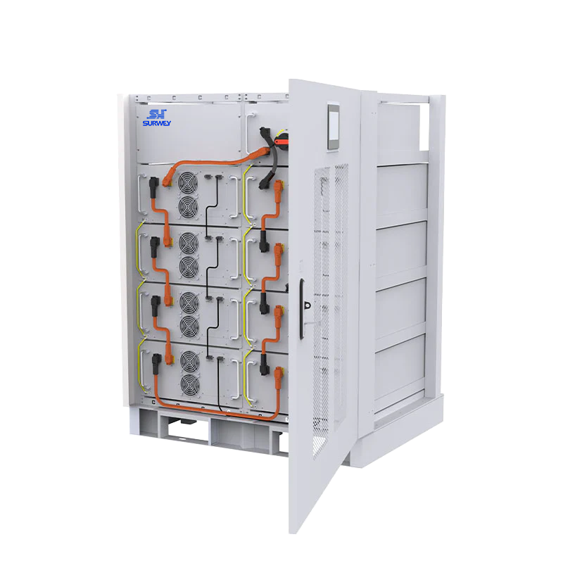
SW-G8-128KWH High-Voltage Rack-Mounted Lithium Iron Phosphate Battery
4.2 Capacity Configuration and Installation Location
The battery has a rated capacity of 128.6 kWh. Taking into account a cycle life based on a depth of discharge (DOD) of 85% to 90%, the actual daily usable capacity is approximately 112 kWh. Based on an average daily electricity consumption of 200 kWh, this capacity can cover roughly half a day’s basic electricity needs or fully support high-priority loads at night when the solar panels are not generating power.
From an energy balance perspective, with an average daily PV generation of 250 kWh and a load consumption of 200 kWh, the surplus of approximately 50 kWh during the day is charged into the battery; at night, the load is supplied by the battery, and the battery is recharged to full capacity by the PV system the following day, forming a complete daily cycle. During consecutive days of rain or overcast weather when PV generation decreases, the battery can be recharged from the grid to maintain a constant state of readiness. In off-grid scenarios where the grid is completely interrupted, a fully charged battery combined with that day’s PV generation can support basic electricity needs for several days.
The SW-G8-128KWH has external dimensions of 530 mm wide, 800 mm deep, and 2,420 mm high, and weighs approximately 1,060 kilograms. The unit stands 2.42 meters tall, while the basement’s clear height is only 2.30 meters, making vertical installation impossible. Therefore, it is recommended to install the battery bank on a terrace area with retaining walls; a 17-square-meter space can accommodate the battery cabinet and power distribution equipment while allowing for a maintenance aisle.
V. Technical Solutions for Grid-Connected Inverters
5.1 Core Parameters and Network Mixing Functionality
The inverter selected is a 55 kW three-phase grid-tied inverter compliant with U.S. standards, with a rated AC output of 55 kilowatts and a maximum apparent power of 60.5 kilovolt-amperes. It supports the U.S. voltage standard.
The DC side is configured with two MPPT trackers and a total of 10 PV string input interfaces, with a maximum input current of 32 to 40 amps per channel. This project connects 8 PV string circuits, with each string operating at a current of approximately 15.65 amps—well below the per-channel current limit, ensuring ample margin. The MPPT voltage range is 180 to 550 volts, with a start-up voltage of 195 volts and a maximum open-circuit voltage of 630 volts. This wide voltage window ensures efficient tracking under varying irradiance levels and ambient temperatures.
The core value of a hybrid inverter lies in its seamless switching between grid-tied and off-grid modes. In normal grid-tied mode, power is supplied jointly by the PV system and the utility grid, while the battery is charged and discharged according to a predefined strategy. When a grid outage or power quality anomaly is detected, the system automatically switches to off-grid standby mode within 16.6 milliseconds, providing uninterrupted power to sensitive loads such as computers and lighting.
In off-grid mode, the rated backup output power remains at 55 kilowatts, supporting 100% three-phase unbalanced loads. This is particularly important for residential projects—where household loads are predominantly single-phase and exhibit high three-phase imbalance. Conventional inverters may limit current or shut down under such conditions, whereas the American Standard 55 kW three-phase hybrid grid-tied inverter’s full imbalance capability ensures that each phase independently outputs one-third of the rated power, with a maximum of 18.3 kW per phase, fully meeting the power consumption characteristics of villa-style buildings. In terms of overload capacity, it can operate continuously for extended periods at up to 110% of rated power and sustain 110% to 120% for 10 minutes, easily handling the startup surges of motor-driven equipment such as air conditioners and water pumps.
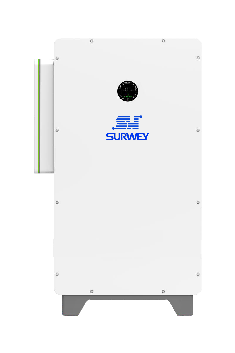
55 kW Three-Phase Grid-Tied Inverter (U.S. Standard)
5.2 Security Protection and Monitoring
Comprehensive safety protection features. The DC side is equipped with PV reverse connection protection, insulation resistance monitoring, ground fault monitoring, string monitoring, PID recovery, and optional AFCI arc fault protection. The AC side is equipped with AC short-circuit protection, anti-islanding protection, and residual current monitoring. Both the AC and DC sides are equipped with Type II surge protectors.
With an IP66/NEMA 4X protection rating, the system is suitable for direct outdoor installation. The intelligent air-cooling system automatically adjusts fan speed based on load and temperature, balancing heat dissipation and noise levels. The operating temperature range is -30°C to +60°C; derating begins at temperatures exceeding 50°C, making it fully adapted to Mexico’s climate. The system is rated for altitudes up to 4,000 meters; since the Bravo Valley is well below this elevation, no derating is required.
For monitoring, the unit comes standard with an OLED display and LED status indicators. Integrated Wi-Fi supports mobile app and cloud-based remote monitoring, with optional 4G or LAN interfaces available. Users can view power generation, electricity consumption, battery SOC, and system status in real time, and can also remotely configure charging and discharging strategies. Operations and maintenance personnel can perform remote fault diagnosis and firmware upgrades via the cloud platform. The inverter also supports a remote control interface for diesel generators, allowing for future integration with generators to form a microgrid system.
VI. Electrical Systems and Compliance with U.S. Standards
The electrical system is designed in accordance with the National Electrical Code (NEC) and local Mexican standards to ensure grid-connection compliance. The grounding system uses a three-phase, four-wire configuration with a protective earth (3P4W+PE). The 110-volt circuit supplies lighting and low-power loads, while the 220-volt circuit powers high-power equipment such as air conditioners and water heaters. An AC distribution panel is installed on the inverter output side, incorporating a main circuit breaker, branch circuit breakers, surge protectors, and metering devices.
DC cable sizing is calculated based on operating current and voltage drop. A 6-square-millimeter DC cable designed specifically for photovoltaic systems is used from the strings to the combiner box, while a 25-square-millimeter DC cable is used from the combiner box to the inverter. All DC connectors use MC4 standard connectors to ensure waterproofing and reliable contact. DC cables are routed entirely through conduit or along cable trays to prevent direct sunlight from accelerating aging.
Lightning protection and grounding are organized into three levels of protection. The PV array mounting structures and metal components are reliably grounded; DC surge protectors are installed inside the combiner boxes; and Type II surge protection is provided on both the AC and DC sides of the inverters. The system features a unified grounding grid, with grounding resistance meeting local code requirements. For seasons with frequent thunderstorms on the Mexican Plateau, a comprehensive lightning protection design is essential for long-term, reliable operation.
The grid-connection interface includes a designated mounting location for a bidirectional energy meter to measure both feed-in and off-grid electricity separately. The specific grid-connection procedures must be coordinated with the local utility company in advance. The design takes into account common grid-connection technical requirements, such as a power factor adjustment range of -1 to +1 and a harmonic distortion rate of less than 3%, all of which comply with mainstream grid-connection standards.
VII. Electricity Generation and System Energy Efficiency
Based on meteorological data from the Bravo Valley, the average annual daily electricity generation of the 57.2-kilowatt photovoltaic array is approximately 250 kilowatt-hours. This estimate takes into account various derating factors, including panel tilt angle, temperature losses, shading losses, cable losses, inverter efficiency, and dust-related losses. On an annual basis, total electricity generation is approximately 91 megawatt-hours, with an average annual equivalent utilization of about 1,590 hours, which is considered above average for central Mexico.
Regarding the system’s overall efficiency, the inverter has a maximum efficiency of 98.2%, with a combined European efficiency of approximately 97.5%; DC-side line losses and mismatch losses account for about 2% to 3%; annual temperature losses are approximately 3% to 5%; and dust-induced shading losses are about 2% to 3%. When these factors are combined, the system’s overall Performance Ratio (PR) is approximately 82% to 85%, indicating a well-designed distributed PV system.
From an energy balance perspective, the system generates an average of 250 kWh per day and consumes 200 kWh, resulting in a very high self-consumption rate. Under an ideal operating strategy, the PV system directly supplies approximately 120 to 140 kWh to the load during the day, with the excess 110 to 130 kWh charged into the battery; at night, the battery discharges 60 to 80 kWh to meet the load, with the remaining electricity serving as a backup buffer. The following day, the PV system recharges the batteries, completing a daily cycle. If a peak-off-peak tariff arbitrage strategy is implemented, electricity can be purchased from the grid during off-peak hours and discharged for self-consumption during peak hours, further enhancing economic efficiency.
The charging and discharging efficiency of the energy storage system is estimated at 90%. When combined with inverter conversion losses, the overall round-trip efficiency is approximately 85% to 88%. With one complete charge-discharge cycle per day and approximately 365 cycles per year—far below the design lifespan of 6,000 cycles—the annual battery degradation rate is manageable, and the capacity retention rate is expected to remain above 80% after 10 years.
VIII. System Expansion, Operations, and Maintenance Warranty
The design fully accounts for future expansion needs and allows for upgrades in multiple dimensions. The PV-side inverter has a total of 10 PV inputs; currently, 8 are in use, leaving the remaining 2 completely idle. In the future, two additional strings—comprising 22 modules with a total installed capacity of approximately 14.3 kilowatts—can be added. The modular design of the energy storage battery bank allows for direct parallel expansion without the need to replace the inverter. Larger-scale upgrades can be achieved by parallel-connecting multiple inverters, allowing for a maximum system capacity of 165 kilowatts.
Regarding warranties, the modules come with a 15-year product warranty and a 30-year linear power warranty; power degradation does not exceed 1% in the first year and 0.35% annually thereafter. The inverter’s standard 5-year warranty can be extended to 10 years, and the battery has a 5-year warranty. Daily operation and maintenance primarily rely on remote monitoring, supplemented by periodic on-site inspections. Real-time monitoring of operational status is conducted via a mobile app and cloud platform, with automatic alerts sent in case of anomalies. On-site inspections are conducted every six months to one year, focusing on module cleanliness, mounting structure tightness, cable aging, inverter filters, battery ventilation, and grounding reliability.
Overall, this 55 kW/128 kWh grid-connected energy storage system fully integrates the project’s on-site conditions with electricity demand, with equipment selection, electrical design, and expansion planning all meticulously optimized. Upon completion, the system will not only significantly reduce electricity costs but also provide reliable backup power, markedly enhancing the quality of life and energy independence. The entire solution features mature technology, reliable equipment, and ample room for future upgrades, making it the optimal technical solution for this project.