Actual photos of the factory grounds
In regions with weak power grid infrastructure, severe voltage fluctuations, and frequent unexpected power outages, factories consistently face the critical challenge of an unstable “power lifeline.” Unannounced power outages can directly lead to production line shutdowns, damage to precision equipment, raw material wastage, and order delays. Meanwhile, the traditional backup power solution using diesel generators suffers from multiple drawbacks, including high fuel costs, cumbersome operation and maintenance, poor power quality, and pollution emissions, severely limiting enterprises’ ability to maximize production capacity and improve operational efficiency. More critically, areas with weak power grids are often plagued by complex grid issues such as voltage sags, harmonic distortion, and three-phase imbalance, which standard power supply systems struggle to accommodate, further exacerbating production risks.
How the 1.1 MW Integrated Off-Grid and Grid-Connected Solar-Storage Solution for Industrial Facilities Works
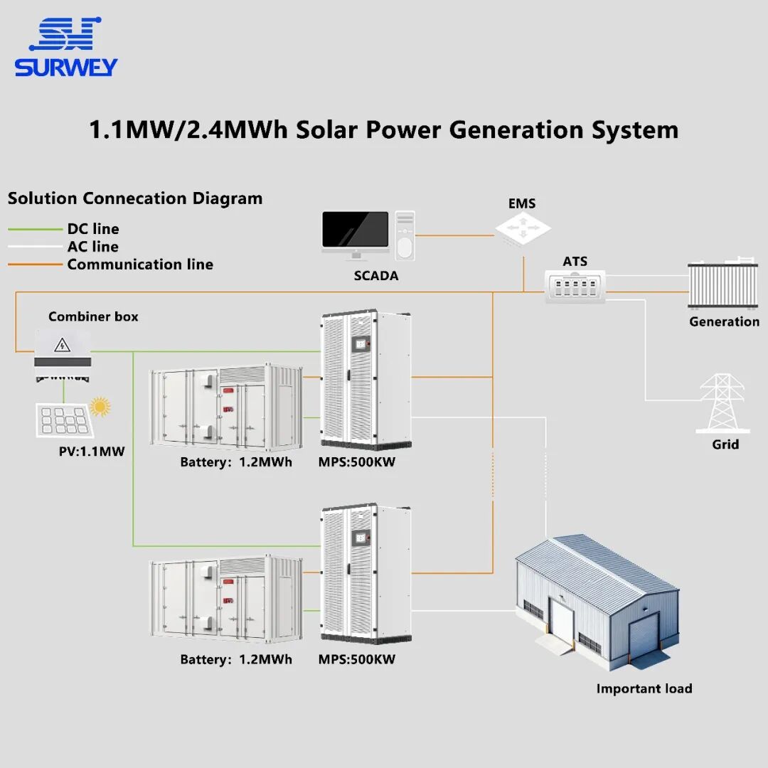
Given the site’s total load of 2.2 MW and the operational requirement for independent power supply in separate zones, this solution establishes a 1.1 MW integrated grid-connected and off-grid power supply system combining solar and energy storage. Centered around an industrial-grade hybrid grid-tie inverter and supplemented by containerized energy storage systems for parallel capacity expansion, the system provides reliable, round-the-clock power support for the site’s core production area (Zone A, 1.1 MW load); The auxiliary zone (Zone B, 1.1 MW load) continues to use the existing utility grid infrastructure, creating a flexible power supply model where “PV and storage safeguard the core, while the utility grid provides supplementary support.” In the event of a utility grid outage or disruption, the PV-storage system seamlessly switches to independent power supply, completely eliminating reliance on an unstable grid. This solution offers highly reliable, low-cost, and easy-to-maintain distributed energy solutions for industrial and manufacturing enterprises in various regions worldwide with weak grid infrastructure.
Topology Diagram of a 1.1 MW Integrated Off-Grid Solar-Storage Solution for Industrial Facilities
I. Core Design Logic of the Solution: Adapting to Complex Power Grids and Establishing a Dual-Circuit Power Supply Architecture
The total load of this project’s facility is 2.2 MW. It employs a zoned, independent power supply architecture that divides the electrical load into a core production area (Zone A) and an auxiliary functional area (Zone B), thereby achieving physical isolation and independent operation of the power supply systems. This approach fundamentally mitigates the impact of single-point grid failures on production across the entire facility. The 1.1 MW core load in Zone A (including precision machining equipment, automated production lines, and critical control systems) is exclusively powered by a hybrid photovoltaic-storage system, ensuring continuous production. The 1.1 MW auxiliary load in Zone B (such as office spaces, lighting, and non-core auxiliary equipment) relies on the local public grid. The two systems are physically isolated via independent distribution panels, ensuring they do not interfere with one another while providing flexible mutual support.
Configuration Diagram for a 1.1 MW Integrated Off-Grid Solar-Storage Solution for Industrial Facilities
The design is based on three core principles: strong grid adaptability, precise power matching, and seamless switching between grid-connected and off-grid modes. It has also been extensively optimized to address the characteristics of weak grids:
Enhancing Grid Resilience
With its wide voltage tolerance design (320–460 V) and active voltage compensation algorithm, the inverter can handle grid voltage fluctuations of ±20%. It also integrates an active power filter (APF) function to actively suppress grid harmonics (THDi < 3%) and improve three-phase imbalance (≤2%), thereby preventing damage to critical equipment caused by grid pollution;
Dynamic Power Matching
Based on the facility’s 24-hour load curve (e.g., morning peak from 8:00 to 10:00 and evening peak from 18:00 to 20:00), a “PV power forecasting + dynamic energy storage regulation” strategy is employed. AI algorithms are used to predict fluctuations in PV output, allowing for advance adjustments to the charging and discharging power of the energy storage system. This ensures that the load power gap remains ≤5% and prevents equipment shutdowns caused by voltage fluctuations;
Seamless Switching Technology
By utilizing STS static transfer switches combined with inverter virtual synchronous machine technology, voltage, frequency, and phase are maintained with millisecond-level synchronization during switching, enabling “zero-impact” switching and preventing sensitive loads (such as PLC controllers and servo motors) from malfunctioning due to power disturbances during the switching process.
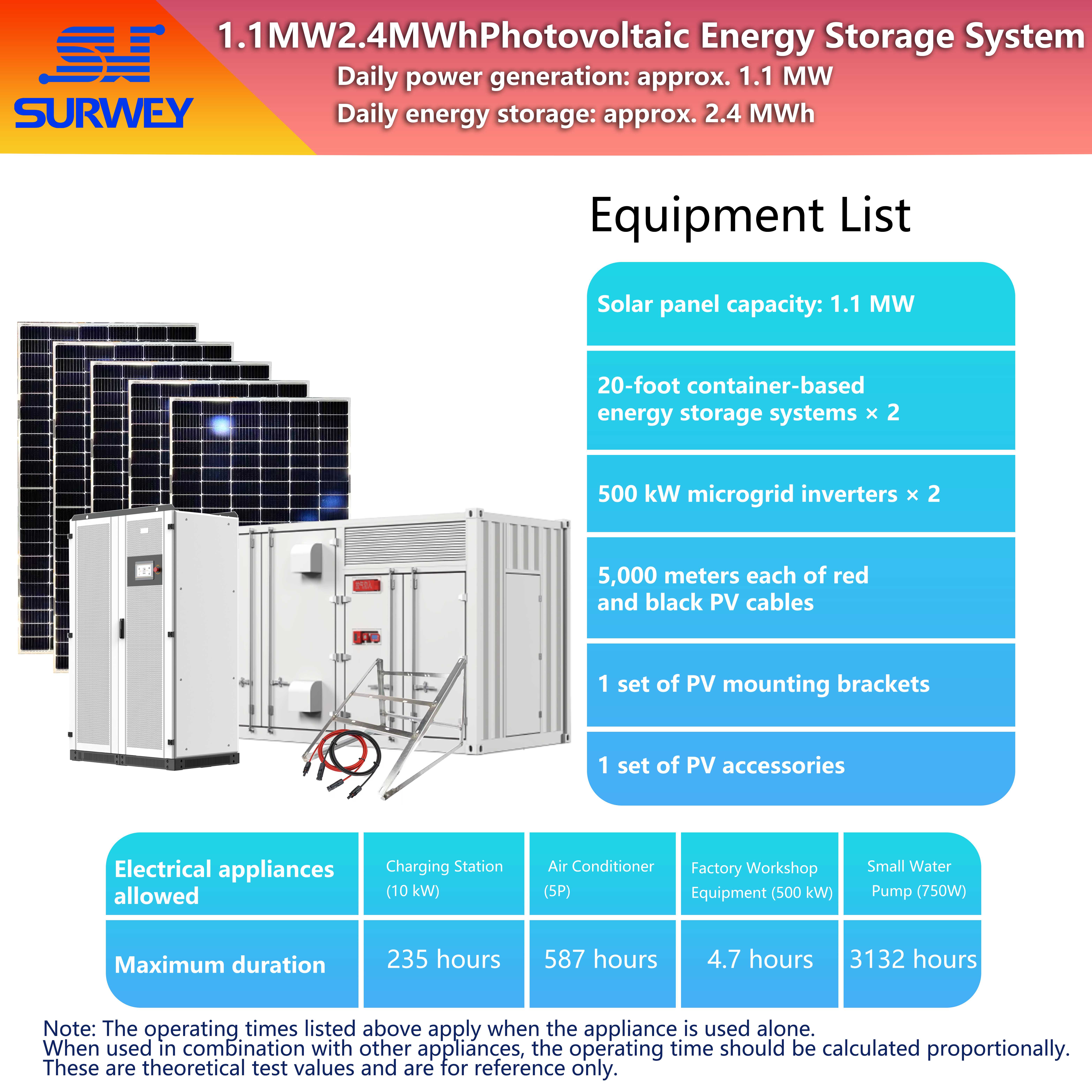
The photovoltaic installed capacity is configured to a standard of 1.1 MW, utilizing a hybrid layout of “distributed rooftop + centralized arrays” to maximize the use of available space on the plant premises; A 1.2 MWh containerized energy storage unit is integrated with the system. Combined with inverter parallel operation and capacity expansion technology, this setup addresses the intermittent nature of solar power, smooths out fluctuations in power generation, and accommodates electricity demand across all time periods—including variations in daylight during the day and the absence of sunlight at night—to ensure a stable 24-hour power supply for the facility.
II. Selection of Core Equipment: Designed to Handle Complex Operating Conditions and Withstand Harsh Environments Across Multiple Scenarios
As the “heart” of the system, grid-tied inverters directly determine power supply stability and environmental adaptability. This solution employs an industrial-grade 500kW grid-tied inverter that integrates an MPPT module, isolation transformer, STS static transfer switch, maintenance bypass, and active filter unit into a single unit. Designed specifically for weak grid and complex load scenarios, it complies with industrial power supply standards across multiple regions worldwide. Its technical principles and core performance breakthroughs are as follows:
1. Advantages of Topology Design
The “three-phase, three-level NPC topology” reduces switching losses by 40% compared to traditional two-level topologies, with a total harmonic distortion (THDi) of less than 3%, resulting in superior power quality; It integrates an isolation transformer (ratio 400V/400V) to provide electrical isolation between the system and the utility grid, preventing grid-side faults (such as lightning strikes and surges) from propagating to the load side. It also suppresses the injection of DC components into the grid, thereby protecting the factory’s precision equipment.
2. Core Performance Adaptability (In-Depth Technical Analysis)
Wide-voltage / wide-frequency operation
AC-side voltage operating range: 320–460 V. Through an active voltage regulation algorithm, the unit maintains rated power output even when the grid voltage drops to 320 V and can withstand grid voltage fluctuations of ±20%. It supports dual-frequency operation at 50/60 Hz; via software-based adaptive adjustment, it can accommodate the frequency requirements of different national power grids (such as 60 Hz in North America and 50 Hz in Europe/Asia) without the need for hardware modifications.
High Power Quality Control
Equipped with a built-in Active Power Filter (APF) function, it detects grid harmonics (2nd to 31st order) in real time and actively compensates for them, with a compensation capacity of up to 10% of the rated power. This effectively suppresses harmonic pollution generated by nonlinear loads such as motors and variable frequency drives, ensuring the normal operation of sensitive equipment such as PLCs and sensors; The power factor is continuously adjustable between 1 leading and 1 lagging. Through reactive power compensation, it stabilizes system voltage and prevents voltage sags caused by reactive power demands from the load.
Strong load-adaptive capability
Supports operation under 100% unbalanced loads (e.g., 30% load on Phase A, 50% on Phase B, and 20% on Phase C). Through an independent phase current control algorithm, it ensures balanced voltages across all phases, preventing equipment overheating or failure caused by unbalanced loads; Capable of withstanding 110% continuous overload (for 24 hours) and 120% short-term overload (for 1 minute). Utilizing dynamic current limiting technology, it can handle 2–3 times the inrush current during motor startup, preventing the system from triggering protective shutdowns.
Flexible Scalability and Integrated Control
Supports up to 8 inverters operating in parallel, utilizing a dual-mode system of “master-slave control + masterless backup.” In the event of a master inverter failure, the system automatically switches to the backup control logic, eliminating the risk of a single point of failure in the parallel system; It features a load factor control function for diesel generators (DG). By communicating in real time with the generator’s ECU via CAN bus, it adjusts the energy storage system’s charging and discharging power to stabilize the generator’s load factor within the optimal range of 60%–80%, reducing fuel consumption by 15%–20% and minimizing carbon buildup and wear on the generator.
3. Alignment of PV and Battery-Side Technologies
PV Input Optimization
Supports up to 1000V PV input (high-voltage architecture), reducing cable losses by 50% compared to 600V architectures, thereby lowering cable costs and installation labor; comes standard with 8/9/10 MPPT modules (optional), with an MPPT voltage range of 250–1000V. It employs a “Maximum Power Point Tracking + Shading Optimization” algorithm, ensuring that even if some modules in the PV array are shaded, the remaining modules continue to operate at their maximum power point, increasing power generation by 8%–12%. It adapts to sunlight conditions across different latitudes and roof layouts worldwide.
Battery Compatibility
Supports connection to batteries with a wide voltage range of 420–950 V and is compatible with mainstream lithium iron phosphate and ternary lithium (customization required) energy storage batteries, eliminating the need for an additional DC/DC converter; Maximum charging power of 550 kW, utilizing a three-stage charging strategy of “constant current – constant voltage – float charging,” combined with a battery temperature compensation algorithm to prevent overcharging in high-temperature environments and extend battery cycle life; features a battery balancing management interface that can interface with the BMS to achieve cell-level balancing, ensuring battery pack consistency.
(2) Energy Storage Unit: 20-foot container-based 1.2 MWh energy storage system
20-foot container-based 1.2 MWh energy storage system
As an “energy warehouse,” energy storage systems perform three core functions: smoothing out fluctuations, peak shaving and valley filling, and off-grid backup. They are essential for ensuring uninterrupted power supply. This solution employs a 20-foot containerized 1.2 MWh lithium iron phosphate energy storage system, specifically designed for complex outdoor environments. It requires no dedicated equipment room and is suitable for climatic conditions in multiple regions worldwide. Its key technical features are as follows:
1. Battery Modules and Safety Design
The system utilizes Grade A lithium iron phosphate cells, with a core configuration consisting of 75 parallel-connected 51.2V/314Ah lithium-ion battery packs. Each pack achieves an energy density of 150 Wh/kg, and the total system energy precisely meets the 1.2 MWh design requirement. The cells have a cycle life of 6,000 cycles (80% DOD), a design service life of 15 years, and a 5-year warranty. The modules employ a “2P32S” series-parallel structure and are equipped with pressure relief valves and temperature sensors; each module is individually encapsulated to prevent thermal runaway. The battery packs are secured in layers using 80 high-strength racks made of Q235B carbon steel. The racks undergo acid washing, phosphating, and powder coating, achieving an IP65 protection rating and a seismic resistance rating of ≥8, capable of withstanding mechanical shocks during transportation and outdoor installation.
The interior of the container integrates five high-voltage cabinets, responsible for battery zone busbar collection, voltage monitoring, insulation testing, and charge/discharge control, respectively. Each high-voltage cabinet houses core components such as fuses (rated current 800A), contactors (breaking capacity ≥10kA), and pre-charge resistors, enabling zone-specific fault isolation to prevent the propagation of single-point failures; It is also equipped with a dedicated fire suppression system (heptafluoropropane fire extinguisher), intelligent temperature-controlled air conditioning (cooling capacity ≥5 kW), flame-retardant cables (YJV22-0.6/1kV), and cable trays. The cabling features a redundant design with a current-carrying capacity margin of ≥30%, while the trays provide fireproofing, rodent protection, and corrosion resistance to ensure standardized and safe internal wiring. The entire container is designed to meet IP54 protection standards. The container body is constructed from Q235B steel specifically designed for shipping containers, with a surface coated in an anti-corrosion finish. It can withstand harsh environments such as salt spray and dust, and is suitable for various climatic regions, including high temperatures (50°C), high humidity (85% RH), and low temperatures (-10°C).
2. Thermal Management and Efficiency Optimization
The system employs a coordinated cooling solution combining “forced air cooling and intelligent temperature-controlled air conditioning.” The airflow path design has been optimized using CFD (Computational Fluid Dynamics) simulations, and the air conditioning and air cooling systems work in tandem to regulate temperature. ensuring internal temperature uniformity of ≤±3°C to prevent battery performance degradation caused by localized overheating; the system achieves a charging and discharging efficiency of 96% (AC-AC), with a battery pack efficiency of 98% and a PCS conversion efficiency of 97.5%; the depth of discharge (DOD) reaches 90%, resulting in a 5.8% increase in actual usable capacity compared to the industry average (85% DOD); The total energy storage capacity of 2.4 MWh can support full-load operation of the 1.1 MW load in Zone A for 2.1 hours.
3. Smart Integration and Monitoring
Integrated with an intelligent BMS (Battery Management System) featuring a sampling accuracy of ≤±0.5%, it monitors parameters such as voltage, current, temperature, SOC (State of Charge), and SOH (State of Health) for each battery cell in real time, and provides multiple protection functions including overvoltage, undervoltage, overcurrent, overtemperature, short-circuit, and insulation monitoring; It interfaces with the inverter in real time via RS485 and CAN communication protocols, with a response time of ≤100 ms, enabling dynamic adjustment of charging and discharging power; it supports communication protocols such as Modbus, TCP/IP, and IEC 61850, allowing integration with plant EMS energy management systems or third-party cloud platforms to enable remote monitoring, data collection, fault alerts, remote diagnostics, and parameter configuration, thereby reducing the complexity of O&M for overseas projects.
20-foot container-based 1.2 MWh energy storage system
(3) Clustering and Capacity Expansion Design: Dual-server coordination to meet high-load demands
To cover the 1.1 MW core load in Zone A, the solution employs a configuration consisting of two 500 kW grid-connected inverters operating in parallel and two 1.2 MWh energy storage containers connected in parallel. The core technical safeguards are as follows:
Inverter Synchronization Control
Using a “sag control + virtual impedance” algorithm, the system achieves power sharing accuracy of ≤±2% across multiple units. When paralleled, the system has a total rated power of 1,000 kW and a peak power of 1,100 kW, fully meeting the 1.1 MW load demand. The parallel system supports “hot-swap” functionality, allowing for maintenance of individual inverters without interrupting power supply, thereby ensuring continuous power delivery;
Parallel Connection of Energy Storage Containers
The two 1.2 MWh energy storage containers achieve voltage and current synchronization via a parallel cabinet. The BMS system employs a master-slave architecture, with the master BMS centrally coordinating the charging and discharging strategies of both containers to prevent circulating currents; The total energy storage capacity reaches 2.4 MWh. Charging and discharging priorities can be configured via the EMS system to smooth out fluctuations in daytime PV output (fluctuation range ≤ ±5%) while ensuring a stable power supply at night when there is no PV output.
III. System Operation Mode: Intelligent switching across multiple scenarios to accommodate electricity demand at all times
EMS Human-Machine Interface
(1) Grid-connected operation mode: Self-generation for self-consumption, reducing costs and improving efficiency
When the public grid is operating normally, the system operates in grid-connected mode. The inverter uses PLL (Phase-Locked Loop) technology to maintain synchronization with the grid. The PV array converts solar energy into direct current (DC), which is then converted to alternating current (AC) by the inverter and supplied primarily to the loads in Zone A; When there is excess PV output, the surplus energy is used to charge the energy storage batteries via the inverter. The charging power is dynamically adjusted based on the battery’s State of Charge (SOC)—charging at full power when SOC is <80%, at reduced power when SOC is between 80% and 90%, and stopping when SOC is >90%; When PV output is insufficient, the energy storage batteries automatically discharge to bridge the gap. The discharge power is dynamically adjusted based on the difference between load demand and PV output, eliminating the need for grid intervention. This enables 100% self-generation and self-consumption of PV power, thereby maximizing the reduction in grid electricity costs.
In this mode, the system can also provide reactive power support to the grid through the “reactive power compensation” function, improving the grid’s power factor (from 0.85 to 0.95 or higher), thereby avoiding penalties for failing to meet power factor standards while reducing line losses.
(2) Off-grid operation mode: 10-millisecond seamless switching, continuous power supply
When the utility grid is interrupted, voltage becomes abnormal (outside the 320–460 V range), or frequency fluctuates (outside the 50/60 Hz ±0.5 Hz range), the system uses an STS (Static Transfer Switch) to disconnect from the external grid within 10 ms and seamlessly switch to off-grid mode, with power supplied independently by the PV + energy storage system. At this point, the inverter switches to primary power mode and uses “voltage-source control” to establish an independent grid (400V/50Hz or 60Hz). The PV system continues to generate power, while the energy storage system handles power regulation and serves as a backup power source:
When sunlight is sufficient (PV output ≥ load demand): PV power is prioritized, and excess energy is used to charge the energy storage system;
When sunlight is insufficient (PV output < load demand): The energy storage battery discharges to supplement power, with discharge power dynamically adjusted according to PV output;
At night when there is no sunlight: The energy storage battery provides independent power supply to ensure continuous operation of critical loads.
In off-grid mode, the inverter features “black start” capability, enabling self-startup without an external power source, making it suitable for extreme scenarios where there is no grid coverage or the grid is completely down. It also supports integration with a diesel generator; when the energy storage system’s SOC is <20% and there is no PV output, the generator automatically starts to charge the energy storage system and supplement power to the load, ensuring long-term off-grid operation.
(3) Intelligent Scheduling Mode: Tailored to Your Needs, Efficient Operation
The system is equipped with an intelligent EMS (Energy Management System) that uses AI algorithms to tailor optimal operating strategies based on multidimensional data (such as light intensity, load power, battery SOC, grid voltage/frequency, fuel costs, and time-of-use electricity rates):
During daylight hours (8:00 a.m.–5:00 p.m.)
Prioritize the use of solar power to maximize the proportion of self-generated and self-consumed electricity; use energy storage only to smooth out fluctuations in solar output;
Peak electricity hours (e.g., 6:00 PM–10:00 PM local time)
Discharging energy storage batteries at full capacity to replace expensive grid electricity and reduce electricity costs;
Off-peak hours (e.g., 12:00 a.m.–6:00 a.m. local time)
If the off-peak electricity rate is lower than the cost of diesel, you can use grid power to charge the energy storage system (optional feature) and discharge it during the next day’s peak hours to generate arbitrage profits;
Rainy days / At night
The energy storage system maintains a continuous power supply; when the SOC falls below 20%, it triggers the diesel generator to start up, preventing a power outage for critical loads;
Periods of voltage fluctuations in the power grid
The inverter actively regulates reactive power to compensate for voltage sags and maintain stable voltage at the load end.
The EMS system supports remote monitoring and data analysis, generating reports on daily, weekly, monthly, and annual power generation, electricity consumption, energy storage charge/discharge volumes, and system efficiency to provide data support for enterprise energy management. It also features a fault early warning function that uses big data analysis to predict potential equipment failures (such as battery degradation or inverter module abnormalities), issuing alerts in advance to reduce the risk of downtime.
IV. Key Advantages of the Solution: Universally Applicable, Empowering Value Across All Dimensions
(1) Unparalleled reliability, eliminating losses caused by power outages
Seamless switching between grid-connected and off-grid modes within 10 ms, with zero-impact transitions, completely resolving issues caused by grid instability and sudden power outages, ensuring zero downtime for core production lines;
Industrial-grade equipment operates within a wide temperature and voltage range (-10°C to 50°C, 320 V to 460 V), withstanding complex environments and load surges. The equipment’s Mean Time Between Failures (MTBF) is ≥100,000 hours;
Multi-layered safety protection design (overvoltage, undervoltage, overcurrent, overtemperature, short circuit, insulation monitoring, fire and explosion protection) ensures equipment and production safety, building a robust power shield for core production capacity.
(2) Significantly reduce costs and optimize operational efficiency
Lower energy costs
A 1.1 MW photovoltaic array generates approximately 1.5 million kWh of electricity annually (based on a global average of 1,350 hours of effective sunlight), while Area A consumes approximately 9.68 million kWh of electricity annually (operating 8,800 hours per year). The self-consumption rate of the PV system reaches 15.5%, resulting in annual savings on grid electricity costs of approximately 1.5 million kWh × local average electricity rate (e.g., $0.15/kWh) = $225,000;
Reduced diesel consumption
Replacing traditional diesel generators for power supplementation, based on a diesel generator fuel consumption of 250 g/kWh and a diesel price of $1.50/ L (density 0.85 kg/L), this solution can reduce annual diesel consumption by approximately 1.5 million kWh × 0.25 kg/kWh = 37.5 tons, resulting in fuel cost savings of approximately 37.5 tons ÷ 0.85 kg/L × $1.50/L ≈ $661,800;
Reduced operational costs
Photovoltaic modules come with a 25-year warranty, energy storage batteries with a 5-year warranty, and inverters with a 5-year warranty. The system has a low failure rate and supports remote operation and maintenance, with annual O&M costs amounting to just one-fifth of those for diesel generators, further reducing operating expenses.
(3) Flexible adaptation, universal applicability
The modular design supports on-demand expansion; when future load increases occur, additional inverters and energy storage containers can be directly connected in parallel without the need to reconfigure the system, reducing expansion costs by 30%;
The containerized energy storage system is designed for outdoor installation, eliminating the need for a dedicated equipment room. This reduces civil engineering costs by 50% and shortens the construction cycle (with a lead time of approximately 35 days), making it adaptable to factory site conditions in various regions worldwide;
It is compatible with 50/60 Hz grid frequencies and a voltage range of 320–460 V, meeting power supply standards in multiple countries. It is suitable for use in regions with weak power grids worldwide, including Africa, South America, the Middle East, and Southeast Asia.
(4) Technological Leadership, Industry Benchmark
Integrating advanced technologies such as APF active power filtering, virtual synchronous generator, and AI-powered intelligent scheduling, it addresses complex issues in areas with weak power grids, including voltage fluctuations, harmonic distortion, and three-phase imbalance;
It delivers industry-leading performance with high power quality (THDi < 3%), high power factor (≥0.95), and high system efficiency (96%);
It supports “solar-storage + diesel” multi-energy complementary systems and is suitable for various scenarios, including off-grid and weak-grid environments, providing a replicable and scalable benchmark model for global distributed energy applications.
V. Life-Cycle Cost Analysis
This plan is based on a 25-year lifecycle (the lifespan of photovoltaic modules). The key economic indicators are as follows:
Initial investment
Approximately $1.8 million (including photovoltaic modules, inverters, energy storage systems, installation and commissioning, civil engineering, etc.);
Annual cost savings
$225,000 in electricity savings + $661,800 in fuel savings + $100,000 in O&M cost savings ≈ $986,800;
Payback Period
Initial investment ÷ annual cost savings ≈ 1.82 years, which is significantly lower than the industry average (3–5 years);
Total returns over 25 years
Annual cost savings × 25 years – initial investment ≈ 98.68 × 25 – 180 ≈ $22.87 million;
Carbon emission reduction benefits
The annual electricity generation from the photovoltaic system is 1.5 million kWh. Based on a carbon emission factor of 0.8 kg/kWh for thermal power, this reduces carbon emissions by 1,200 tons annually, resulting in cumulative emissions reductions of 30,000 tons over 25 years. This helps companies enhance their green brand image and aligns with carbon tax policies in certain countries.
VI. Application Scenarios and Industry Value
This solution is suitable for various types of factories in regions worldwide with weak grid infrastructure and unstable power supply, including manufacturing, processing, industrial and mining enterprises, and industrial parks. It is particularly well-suited for core production scenarios that demand high power supply continuity, such as automotive parts processing, electronic equipment manufacturing, food processing, and chemical production.
As a distributed energy solution characterized by “high reliability, low cost, easy operation and maintenance, and universal applicability,” this system not only resolves the power supply challenges faced by factories in areas with weak grid infrastructure but also delivers three key benefits through technological innovation: “stable power supply, cost reduction and efficiency improvement, and flexible adaptability.” It provides core support for enterprises to enhance operational resilience and market competitiveness. In the future, as photovoltaic and energy storage technologies evolve and costs decline, this solution will be implemented in more emerging markets worldwide. It will inject sustained momentum into the stable development of various enterprises in complex power supply environments, driving the widespread adoption of distributed energy and the optimization and upgrading of the global energy structure.
Conclusion: In the context of the global energy transition and the industrialization of emerging markets, a stable and reliable energy supply is key to a company’s core competitiveness. The 1.1 MW integrated on-grid and off-grid solar-storage solution for factories addresses the power supply challenges in weak grid areas through cutting-edge technology, flexible design, and comprehensive adaptability. It builds a new power supply system that is “autonomous, cost-effective, and safe and stable,” helping enterprises navigate complex environments with stability and resilience while improving quality and efficiency.


