
Project Proposal Report for 8.5kW Residential PV-ESS System for a Detached House in Suburban Kenya
I. Project Overview
This project is implemented in a mature residential suburb on the outskirts of Nairobi, Kenya, for a middle-class family of five living in a two-storey detached villa with a private courtyard and a self-provided deep well. The power grid coverage in Nairobi is generally acceptable, yet the terminal voltage fluctuates severely. Power outages occur frequently during peak load periods in the dry season and thunderstorm seasons in the rainy season, each lasting 2 to 8 hours. Frequent blackouts have continuously disrupted household refrigeration, domestic water supply and home office work.
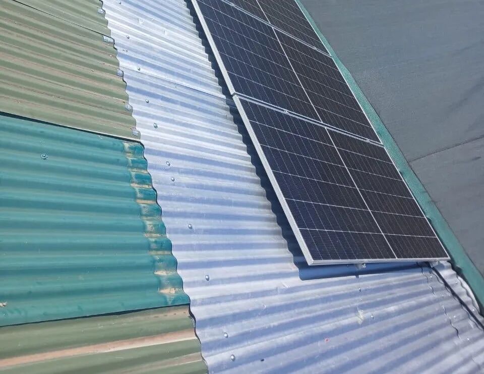
(Solar panel installation photo)
The homeowner previously used a small gasoline generator for backup power. Although it could serve emergency needs, it suffered from delayed startup, noise pollution, troublesome fuel storage and transportation, and even burnt out network equipment due to unstable voltage. The homeowner’s core requirements are clear: first, achieve on-site self-consumption of solar power to cut grid electricity bills; second, enable seamless power backup during blackouts to keep critical home appliances running and completely replace the gasoline generator; third, realize fully automatic unattended operation with real-time status monitoring via mobile phone.
To meet the above demands, we adopt a grid-tied hybrid energy storage system with both grid-connected power saving and off-grid emergency power supply functions. The system configuration includes: 1 set of 8.5kW single-phase hybrid grid-tied inverter, 1 set of 10.24kWh wall-mounted energy storage battery, and 14 pieces of 600W bifacial PV modules.
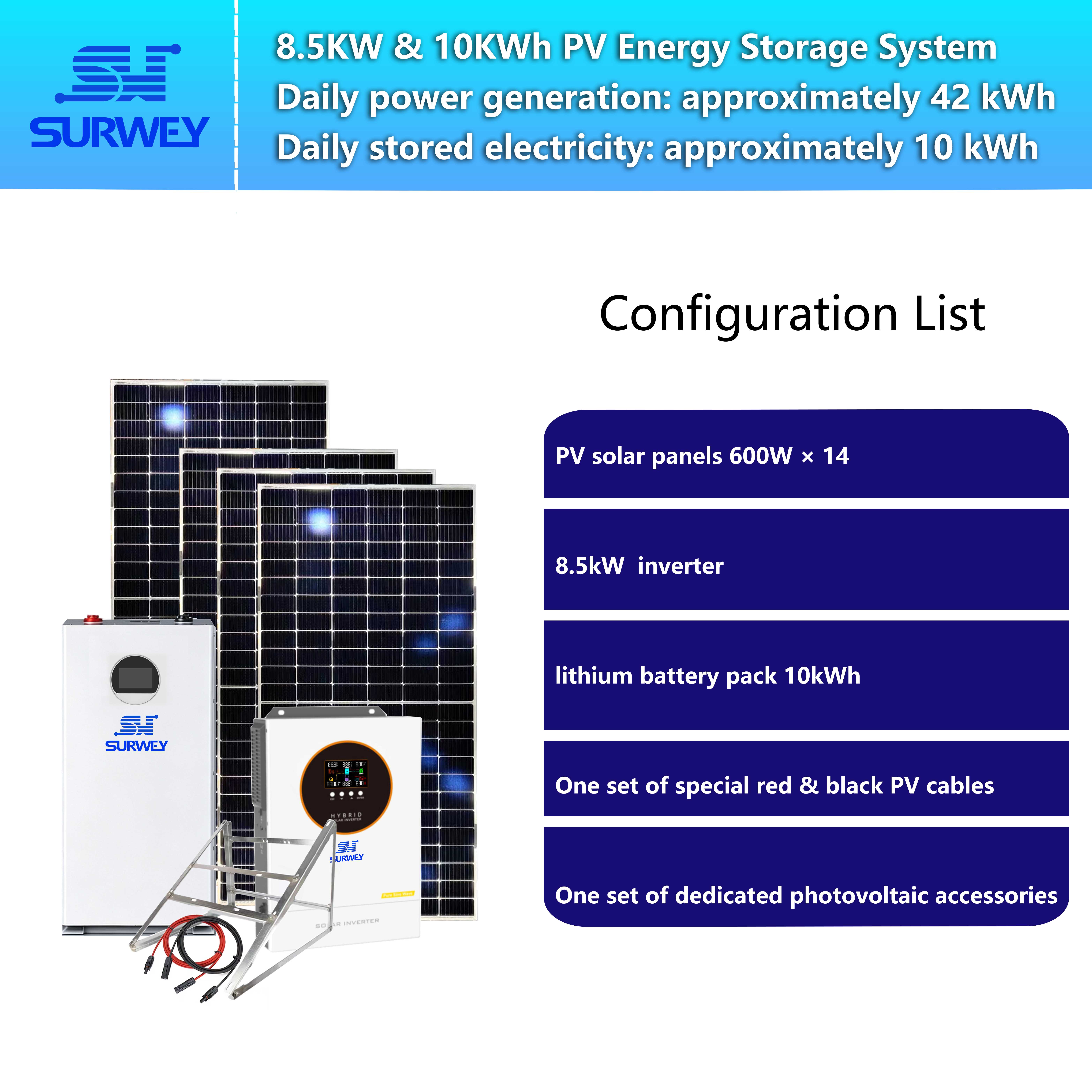
(System configuration diagram)
II. Calculation of Household Electricity Loads
Accurate load matching is the core premise of system design. Based on the homeowner’s appliance list and daily schedule, we calculate daily power consumption and peak load item by item. All equipment selection strictly follows these data to avoid overcapacity waste and insufficient power supply.
| Electrical Equipment | Rated Power | Daily Operating Hours | Daily Power Consumption | Remarks |
|---|---|---|---|---|
| Side-by-side refrigerator + upright freezer | 120W (average) | 24h | 2.88kWh | Continuous intermittent operation |
| 1.5HP split air conditioner (2 units) | 1200W per unit | 6h | 14.4kWh | Operation in afternoon and evening |
| Deep well water pump | 750W | 2h | 1.5kWh | Water pumping in 3 batches daily |
| Kitchen appliances (rice cooker, kettle, oven, etc.) | — | — | 3.2kWh | Concentrated power use during three meals |
| Lighting, TV, router, mobile device charging | — | — | 3.5kWh | Scattered loads throughout the day |
| Weekly-use equipment (washing machine, dryer, etc.) | — | — | 1.2kWh | Averaged daily consumption |
| Total | — | — | Approx. 26.7kWh/day | — |
The peak load concentrates between 19:00 and 21:00 in the evening, when two air conditioners, kitchen appliances, lighting and TV run simultaneously, creating an instantaneous peak load of around 6.2kW. The starting inrush current of the deep well pump reaches 5 times its rated power, which is the key factor to verify the overload margin of the inverter.
III. Core Equipment Selection and Key Parameters
Every parameter is matched to the actual load demand without blindly pursuing oversized capacity, and each specification corresponds to practical application value.
1. Single-phase Hybrid Grid-tied Energy Storage Inverter (SW-8.5KW-48V)
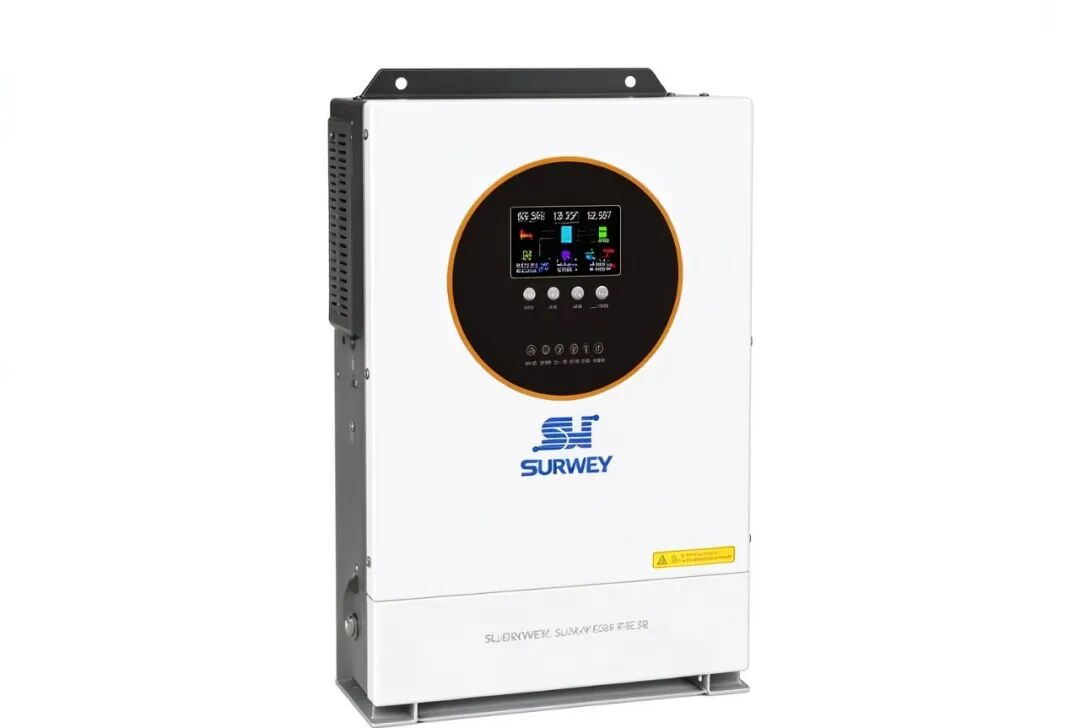
(Single-phase hybrid energy storage inverter photo)
As the control core of the whole system, this unit manages PV rectification, battery charge and discharge, and seamless switching between grid-tied and off-grid modes. Key parameters are as follows:
- Rated output power: 8.5kW, supports 110% continuous overload operation
- PV side: single MPPT channel; MPPT voltage range 60–450VDC; maximum open-circuit voltage withstand 500VDC; maximum PV input power 9kW; maximum PV charging current 140A
- Battery side: compatible with 48V battery pack; maximum charging current 100A; supports BMS communication linkage with lithium batteries
- Grid side: compatible with 230V single-phase mains; grid-tied voltage range 195–253VAC; millisecond-level seamless switching between grid-tied and off-grid modes
- Additional functions: WiFi/GPRS remote monitoring; battery-independent operation; automatic lithium battery activation
Selection Logic: The 8.5kW rated output leaves a 37% power margin above the 6.2kW daily peak load, fully covering the startup inrush of air conditioner compressors and water pumps to prevent overload tripping. The wide grid voltage range (195–253V) adapts to severe terminal voltage fluctuations in Nairobi and avoids unexpected disconnection from the grid. A single MPPT channel delivers sufficient tracking efficiency for rooftop modules with identical orientation and specifications, delivering optimal cost performance.
2. Wall-mounted LiFePO4 Energy Storage Battery (51.2V 200Ah)
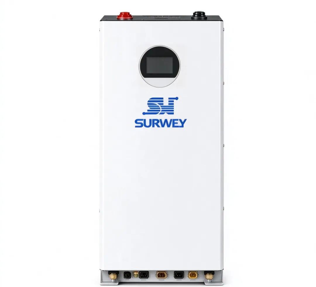
(10kWh energy storage battery photo)
The battery acts as the energy reservoir of the system, determining blackout backup duration and peak-hour power support. Key parameters are as follows:
- Nominal specification: 51.2V / 200Ah, rated energy 10.24kWh
- Charge & discharge capacity: continuous charge/discharge current 0–150A; maximum charge/discharge power around 7.7kW
- Voltage range: charging cut-off voltage 58.4V; discharging cut-off voltage 44.8–46.5V
- Cycle life: ≥6,000 cycles (25℃ environment, 80% depth of discharge)
- Protection & communication: built-in BMS with RS485 & CAN communication; full protection against overvoltage, undervoltage, overcurrent, short circuit and overheating
- Installation form: wall-mounted; total weight 75.1kg
Selection Logic: With a safe discharge depth of 90%, the usable capacity reaches roughly 9.2kWh. This can fully cover 3–4 hours of evening peak consumption or over 12 hours of basic emergency power supply, avoiding both insufficient capacity and idle investment. The wall-mounted design saves indoor storage space, perfectly fitting residential scenarios. With 6,000 charge-discharge cycles (one cycle per day), the theoretical service life exceeds 15 years, matching long-term household usage.
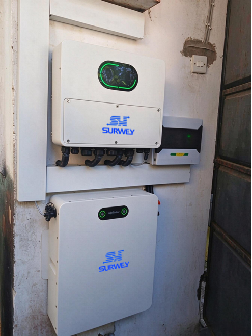
(Indoor installation photo of key PV equipment)
IV. PV Array String Configuration Design
The system adopts 14 identical 600W PV modules. The design principle requires all series strings to have the same number of modules, with string voltage always kept within the inverter’s safe operating window. We avoid overvoltage under low temperature and undervoltage under high temperature to guarantee long-term stable power generation.
1. Verification Logic for String Configuration
PV module voltage varies with temperature: voltage rises sharply when temperature drops, so low-temperature open-circuit voltage is the upper safety limit of the inverter. Voltage falls when temperature rises, so high-temperature operating voltage sets the lower limit for power generation efficiency.
The minimum night temperature in suburban Nairobi is about 8℃, while the maximum module operating temperature at noon hits 65℃. We verify the voltage compliance of different series configurations under these extreme conditions:
| Modules per String | Open-circuit Voltage at 8℃ | Operating Voltage at 65℃ | Equal Split for 14 Modules | Feasibility Result |
|---|---|---|---|---|
| 14 | ~693V | ~508V | 21 strings | Exceeds the 500V voltage limit; high breakdown risk — Rejected |
| 8 | ~396V | ~290V | Cannot split 14 evenly | Voltage compliant but uneven string count causes high mismatch loss — Rejected |
| 7 | ~347V | ~254V | 2 strings (2×7=14) | Voltage stays within safe and efficient range; perfect equal split — Final Scheme |
| 4 | ~198V | ~145V | Cannot split 14 evenly | Voltage compliant but uneven string count causes high mismatch loss — Rejected |
2. Final String Configuration
Final arrangement: 14 modules are divided into 2 series strings with 7 modules each; the two strings are connected in parallel to the single MPPT channel of the inverter.
Under this configuration, the extreme low-temperature open-circuit voltage is only 347V, leaving a 43% sufficient safety margin below the 500V upper limit to eliminate overvoltage breakdown risk. The high-temperature operating voltage of 254V falls well within the inverter’s 60–450V MPPT working range, so power generation efficiency will not drop sharply even under high noon temperatures.
Meanwhile, the total installed capacity of 8.4kW is nearly equal to the inverter’s 9kW maximum PV input limit. The inverter can fully absorb all PV output without peak clipping waste, achieving the optimal power utilization rate.
V. Full-time System Operation Strategy
(System operation principle video)
The whole system runs fully automatically with no manual intervention. We take a typical sunny day to illustrate the energy flow logic for the homeowner.
06:30–08:00 Morning Startup After sunrise, solar irradiance rises and PV voltage reaches the startup threshold, and the system switches on automatically. Only basic loads such as refrigerators and routers are running. PV power first supplies on-site loads, and excess electricity charges the battery.
08:00–12:00 Self-consumption in the Morning Household loads gradually increase while PV output rises simultaneously. Solar power prioritizes kitchen appliances, lighting and daily home equipment, with surplus energy continuing to charge the battery. Grid power consumption is nearly zero during this period.
12:00–15:00 Noon Peak Generation Solar irradiance peaks with maximum PV output. Solar power first covers high-load afternoon air conditioning, and charges the battery at maximum current. Once the battery is fully charged, all PV generation directly feeds household loads, achieving nearly zero grid power consumption.
15:00–18:30 Evening Transition Period Solar irradiance fades in the late afternoon, and the battery is nearly fully charged. PV power continues to supply household loads, with any shortfall supplemented by battery discharge to delay grid power connection as long as possible.
18:30–22:00 Evening Peak: Battery Power Support PV generation stops after sunset, and the system switches to battery discharge mode to power air conditioners, lighting and televisions during evening peak hours. This is the core working scenario for the battery, with zero grid power consumption.
22:00 – 06:30 Next Day Grid Power Backup When the battery state of charge drops to the 20% low-voltage protection threshold, the system automatically switches back to grid power, only maintaining low-power basic loads such as refrigerators. This prevents deep discharge and extends battery service life.
Power Outage Mode: Once the inverter detects mains power failure, it switches to off-grid mode within milliseconds, with power jointly supplied by PV and battery. Household power supply remains completely uninterrupted. The system automatically reverts to grid-tied mode when grid power is restored. The whole switching process is seamless and requires no manual operation.
VI. System Value & Performance Boundaries
Stating both advantages and limitations objectively helps the homeowner form reasonable expectations of the system.
Core Benefits
- Electricity Bill Savings: On typical sunny days, PV and battery cover roughly 80% of daytime and evening peak electricity consumption. Daily grid power purchase can be reduced to only 5–6kWh, cutting annual electricity expenditure by more than 70%.
- Blackout Protection: When fully charged, the system can power basic loads for over 12 hours and peak loads for 3–4 hours, fully covering most blackout durations in Nairobi and permanently replacing gasoline generators.
- Easy Operation: Fully automatic operation with no manual switching or startup. Users can monitor real-time power generation, battery state of charge and household power consumption on mobile phones, with nearly zero daily maintenance cost.
- Long-term Asset Value: PV modules come with a 30-year power output warranty; the battery delivers over 15 years of service life based on cycle life; the inverter has a design lifespan of more than 10 years. The whole system acts as a long-term fixed asset for the household.
VII. Project Summary
This 8.5kW residential PV-ESS system is tailor-made for household power consumption habits and unstable grid conditions in suburban Nairobi. Starting from the daily electricity demand of 26.7kWh, we match an 8.5kW inverter and 10.24kWh battery capacity. Through strict voltage verification, we optimize the 14 PV modules into two strings of 7 modules each. Every parameter corresponds to actual application scenarios, and every design follows the principle of adequate capacity, high reliability and ease of use.
For residential users, a PV energy storage system does not need to be oversized; the best solution is the one that perfectly matches daily life. This scheme avoids overpaying for unused capacity while preventing insufficient power supply. Delivering stable, worry-free power and effectively solving blackout troubles and high electricity bills is the greatest value of this system.


