
Implementation Report on Photovoltaic Energy Storage Emergency Power Supply Project for a Rural Residence in Nigeria
Preface
The power grid in some parts of Nigeria suffers from insufficient stability. Frequent power outages have become commonplace for many households, especially during the rainy season and peak electricity consumption. For families living in rural and township areas, power failures disrupt not only lighting and domestic power use, but also pose direct risks to refrigeration appliances, home medical equipment, communication networks and small-scale productive loads.
This project serves a residential household in a Nigerian township. The client’s regular loads include lighting, refrigerators, internet communications and home medical devices. The client requires emergency power availability during grid outages. Rather than merely seeking to cut short-term electricity expenses, the client intends to enhance the reliability and self-sufficiency of household power supply through a photovoltaic energy storage system.
Subject to site conditions, the original residential distribution wiring is outdated. The client wishes to avoid large-scale rewiring indoors. Accordingly, the system adopts a parallel connection scheme to minimize interference with the existing distribution setup. Photovoltaic modules are deployed on open ground near the building with favourable southward orientation and negligible shading.
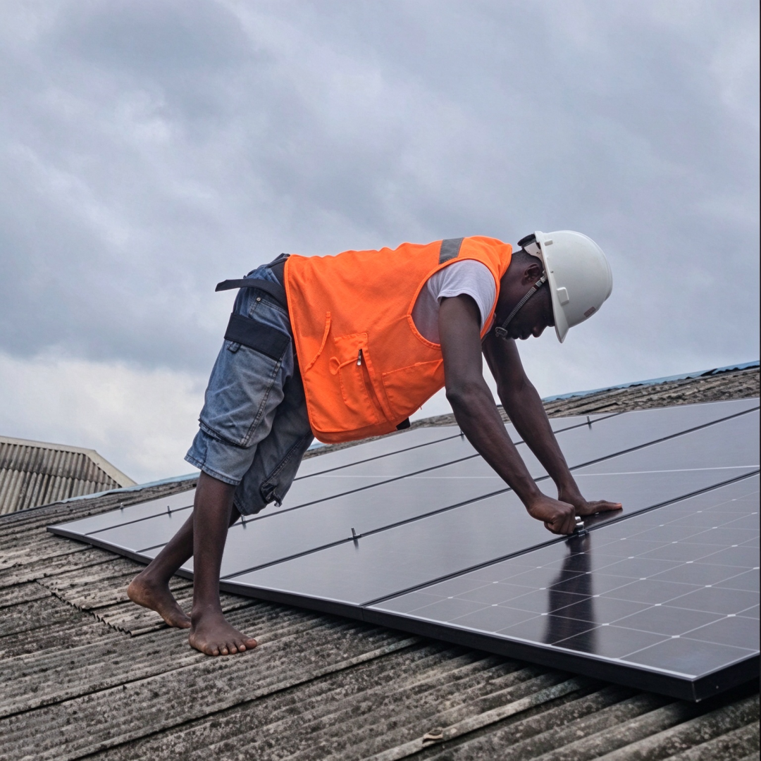
Photovoltaic Module Installation Drawing
1. Project Demand Definition
Based on site surveys and communications with the client, practical requirements have been consolidated as the core design basis for the complete system: First, emergency power supply. Upon grid failure, the system shall seamlessly switch to backup power mode to sustain continuous operation of oxygen concentrators, refrigerators, basic lighting and communication equipment. The night-time critical load ranges from 0.5 kW to 0.8 kW, with a minimum guaranteed runtime of 8 consecutive hours. During overcast periods, non-essential loads may be shed to prioritise core medical equipment. The inverter must achieve an ultra-short transfer time to prevent protective shutdown and restart of compressor loads and medical apparatus.
Second, self-consumption. While the utility grid is available, power generated by photovoltaics shall supply domestic loads on a priority basis. Surplus electricity is stored in the energy storage battery. No export to the public grid is configured, complying with local self-consumption grid-connection codes.
Third, site and construction constraints. No installation shall be carried out on the ageing original roof; all modules are mounted on ground racks. Major renovation of indoor wiring is prohibited, and the system is paralleled into existing distribution circuits for rapid deployment with minimal modifications.
Fourth, environmental adaptability. The project site experiences intense summer heat, which elevates module operating temperatures. The photovoltaic array voltage must remain within the inverter’s safe operating window under low-temperature conditions. The local rural grid sits at the end of distribution lines with wide voltage fluctuations. The inverter shall support a broad mains input range to reduce unintended system cycling triggered by grid disturbances.
2. Selection of Core System Components
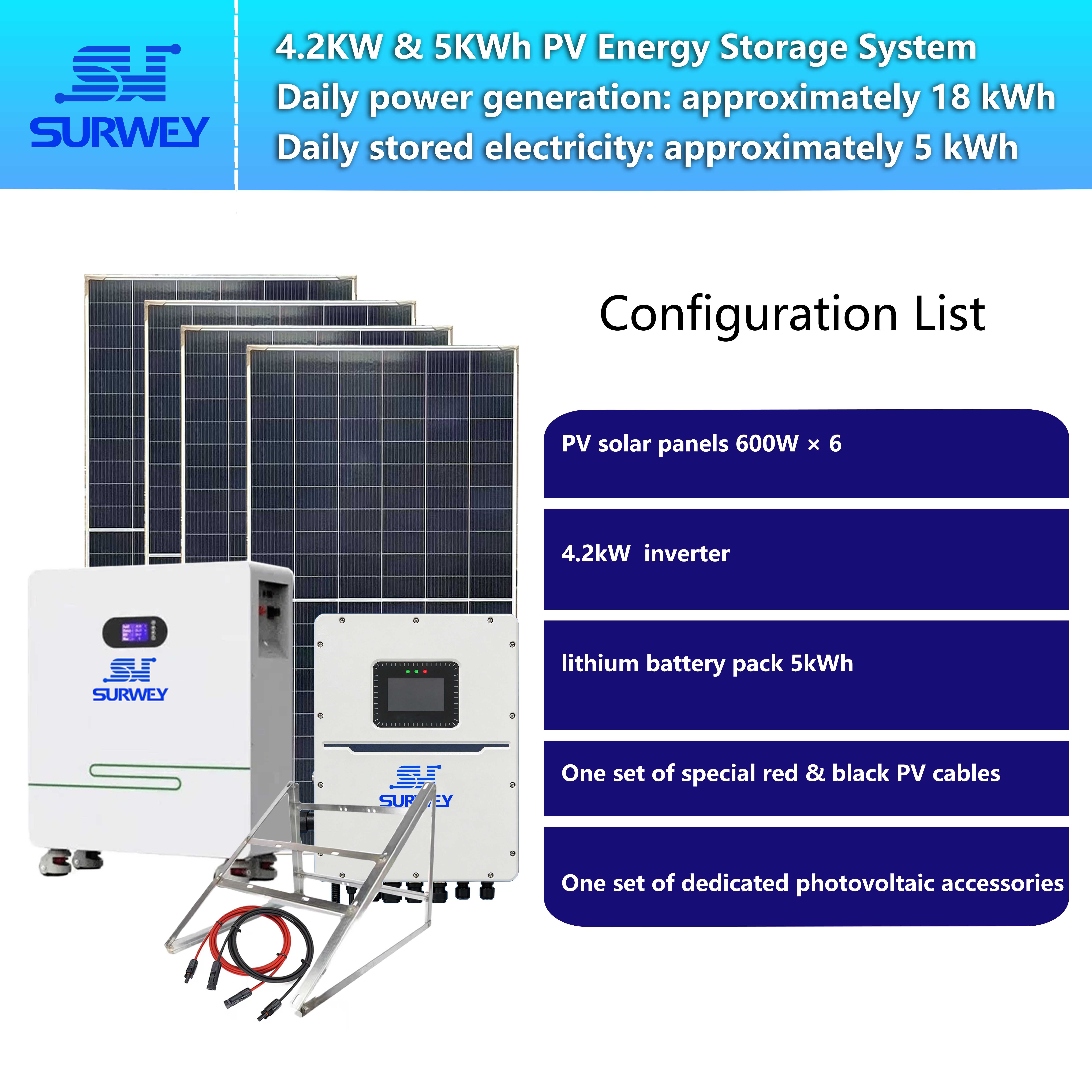
2.1 4.2 kW Single-Phase Hybrid Inverter
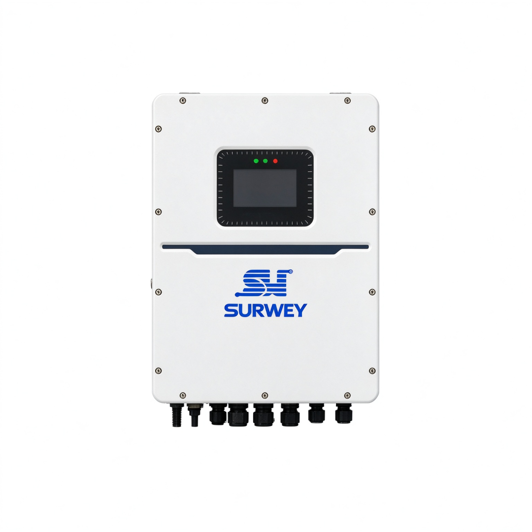
A 4.2 kW single-phase hybrid inverter is selected for this project, built on a 24 V DC platform matching the nominal voltage of the energy storage battery. It delivers a rated output of 4.2 kW and a peak output of 8.4 kW, sufficient to accommodate routine household loads together with high inrush loads such as refrigerator compressors.
The inverter outputs pure sine-wave alternating current, suitable for home appliances, medical devices, lighting and networking hardware. Its mains input supports an extended voltage window to tolerate substantial local grid swings and reduce frequent system transfers caused by transient voltage anomalies.
An integrated MPPT solar charge controller enables efficient maximum power point tracking for photovoltaic modules with a wide photovoltaic input voltage range compatible with series-connected strings. The inverter supports both solar charging and mains charging, and automatically adjusts charging strategies according to grid status.
For emergency transfer, the unit features fast switching to battery-backed operation once the grid drops out, sustaining critical loads without interruption. Comprehensive protective functions including overvoltage, undervoltage, overcurrent, short-circuit and overtemperature protection are incorporated to improve operational safety and reliability.
The inverter supports flexible mounting in outdoor or semi-outdoor ventilated locations, though direct solar irradiation and prolonged rain immersion must be avoided. It shall be installed in a dry, well-ventilated and serviceable location at an appropriate distance from the battery bank and photovoltaic array.
2.2 25.6 V 200 Ah Floor-Standing Energy Storage Battery
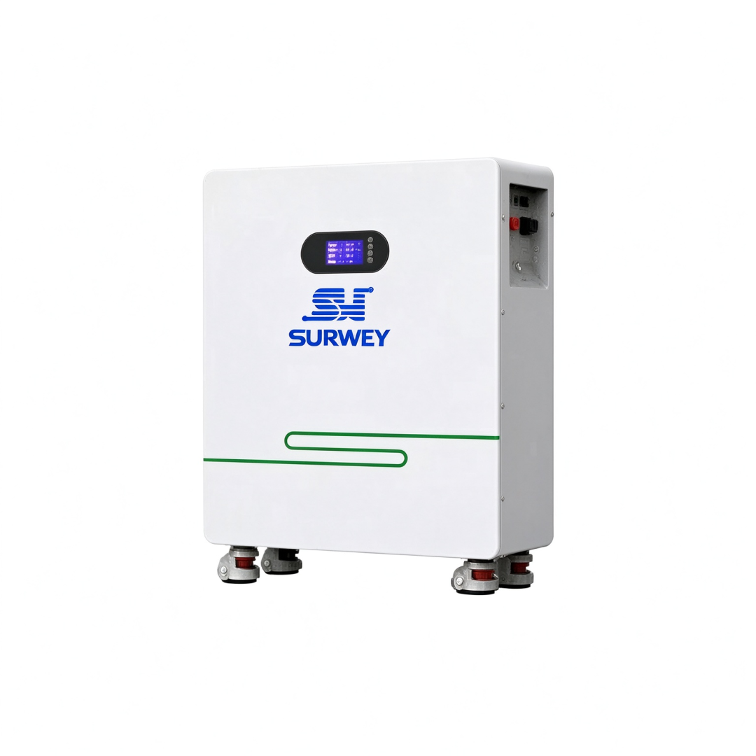
5 kWh Floor-Standing Lithium Iron Phosphate Energy Storage Battery Pack
The energy storage unit adopted is a 25.6 V, 200 Ah floor-standing battery with a usable capacity of approximately 5.12 kWh, belonging to the 24 V energy storage platform and electrically compatible with the inverter’s DC side. Adopting lithium iron phosphate chemistry, the battery boasts a long cycle life ideal for long-term deployment in residential photovoltaic storage systems.
The battery has a nominal voltage of 25.6 V and an operating voltage spanning roughly 22.4 V to 29.6 V. With a 200 Ah capacity, it can power lighting, refrigerators, routers and medical equipment for extended continuous operation under emergency scenarios. To preserve service life and operational safety, the system prevents deep discharge by retaining a residual state-of-charge margin.
An internal battery management system (BMS) continuously monitors cell voltage, total pack voltage, current and temperature, implementing protection against overcharge, overdischarge, overcurrent, short circuits and overheating. Cell balancing functionality maintains consistent conditions among individual cells to extend overall battery lifespan.
The photovoltaic array consists of 600 W N-type bifacial photovoltaic modules with an open-circuit voltage of 47.2 V and an operating voltage of 39.9 V. The bifacial design harvests albedo from the ground to boost energy yield. The modules carry a 30-year linear power warranty for stable long-term generation and integrate bypass diodes to mitigate hot-spot risks induced by partial shading, making them suitable for permanent outdoor exposure.
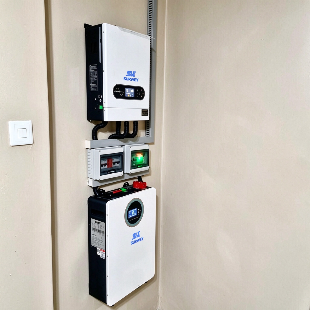
Indoor Installation View of Key Photovoltaic Equipment
3. Photovoltaic Array String Design
Six 600 W photovoltaic modules are deployed in this project. Considering the voltage platform, the inverter’s MPPT operating range and voltage stability under high ambient temperatures, all six modules are wired in a single series string connected to one MPPT channel of the inverter.
Each module features a standard-condition open-circuit voltage of approximately 47.2 V, yielding a total string open-circuit voltage of around 283.2 V for six modules in series. Although module open-circuit voltage rises at low temperatures, verification confirms that the maximum cold open-circuit voltage stays below the inverter’s DC input limit and will not activate overvoltage protection.
Under standard test conditions, each module operates at 39.9 V, bringing the string operating voltage to roughly 239.4 V. High summer temperatures in Nigeria raise module backsheet temperatures and depress operating voltage. Even under extreme heat, the string operating voltage remains within the inverter’s MPPT tracking window, permitting persistent maximum power harvesting.
This configuration delivers a simple architecture with one single photovoltaic array, eliminating voltage mismatch and circulating currents between separate strings. Uniform module model, orientation and tilt angle ensure consistent performance, easing installation, commissioning and ongoing maintenance.
The photovoltaic array is mounted on fixed ground racks oriented close to true south. The tilt angle is optimised according to local latitude and household load profiles. Front-to-rear rack spacing is engineered to avoid mutual shading during morning and afternoon hours. Modules are elevated above ground to enhance capture of ground-reflected irradiance for bifacial gain while facilitating periodic cleaning and vegetation management.
4. System Operating Logic
Video Illustrating System Operating Principles
The system operates on a core principle: photovoltaic power prioritisation, battery energy storage and emergency load assurance.
During daylight with adequate irradiance, electricity generated by photovoltaic modules supplies active household loads first. If photovoltaic output exceeds instantaneous load demand, surplus power is directed through the inverter to charge the battery bank. Once the battery reaches full state of charge, charging terminates to prevent overcharge.
When photovoltaic generation cannot satisfy load consumption, the inverter supplements power drawn from the energy storage battery. If the battery state of charge falls below the predefined cutoff threshold, the system automatically reverts to mains supply to avoid deep battery depletion.
In the event of an abrupt grid outage, the inverter rapidly transfers to backup mode, where the battery bank and photovoltaic array jointly feed critical loads. The short transfer time generally avoids protective shutdown of refrigerator compressors and selected medical equipment.
If an outage coincides with overcast weather and limited photovoltaic output, the system manages power according to remaining battery capacity and active loads. The client is advised to shed non-essential loads voluntarily to preserve supply for refrigeration, lighting, internet and medical devices. Once grid service is restored, the system switches back to grid-tied operation and recharges the battery using both mains power and photovoltaic generation.
Given severe local grid voltage excursions, the inverter is configured for wide-voltage grid-tied operation. Temporary voltage swings will not trigger frequent protective trips, reducing unnecessary battery cycling and extending battery service life.
5. Expected System Performance
Regions across central and northern Nigeria receive high horizontal solar irradiance. For this site, the estimated horizontal irradiation is set between 1600 kWh/m² and 1800 kWh/m². The 3.6 kWp photovoltaic array is projected to yield 5500 kWh to 6200 kWh in its first year of operation.
Energy production fluctuates markedly with seasonal rainfall. Longer sunshine hours in the dry season deliver higher photovoltaic output, while overcast conditions in the rainy season reduce generation. Nevertheless, the array can still supply partial daytime load demand and recharge the battery throughout the wet season.
The household consumes approximately 8 kWh daily, with loads present in both daytime and evening hours. Under this load profile, a large share of daytime consumption can be covered by on-site photovoltaic generation, while stored battery energy supplements evening demand. Self-sufficiency rises substantially during periods of strong irradiance, whereas greater reliance on the utility grid is required in extended overcast spells.
For emergency backup, the 5.12 kWh battery, after accounting for usable depth of discharge and practical load characteristics, sustains the 0.5–0.8 kW critical load block for multiple hours. If the outage occurs during daylight, ongoing photovoltaic generation extends the available runtime. In prolonged cloudy conditions, limited battery capacity necessitates load curtailment to preserve power for priority equipment.
Thermal management of the inverter and battery is critical under high ambient temperatures. During initial trial operation, continuous monitoring of inverter case temperature, battery temperature, MPPT voltage and charging current is required. Excessive equipment temperature calls for inspection of mounting and ventilation; load reduction or additional shading may be implemented where necessary.
6. Future Expansion and Project Summary
The system retains headroom for later expansion. The inverter has residual photovoltaic input capacity. If the client adds loads or requires longer backup duration, extra photovoltaic modules may be installed subject to site constraints. Energy storage capacity can also be upgraded by paralleling identical battery packs for enhanced outage resilience.
Expansion must strictly preserve voltage-platform consistency. This project adopts a 24 V inverter paired with 25.6 V batteries. Devices of incompatible voltage ratings cannot be retrofitted arbitrarily, as mismatched hardware may induce communication faults, irregular charge–discharge behaviour or permanent equipment damage.
The primary objective of this installation is not maximised energy yield, but reliable power assurance for the household. For Nigerian households vulnerable to recurring outages and grid instability, the photovoltaic energy storage system improves routine power autonomy and safeguards essential services including refrigeration, medical support, lighting and communications when the grid fails.
This project reinforces that residential photovoltaic storage design must originate from the client’s genuine operational needs. Definition of mandatory backup loads during blackouts precedes sizing of inverter power, battery capacity and photovoltaic array. Matching voltage platforms, communication protocols and operating windows across inverters, batteries and photovoltaic strings is indispensable for stable long-term operation, turning the installation into a dependable household power safeguard.


