
A Solar-Storage Project Report for a Grain Milling Workshop in Ethiopia: Stabilizing Production for the 11 kW Huller
Preface
In market towns and rural areas across Ethiopia, grain hulling serves as a vital source of income for local farmers. Every harvest season, once corn and sorghum are reaped, hulling must be completed promptly. Any delay amid humid weather risks grain moulding and spoilage, wasting farmers’ hard work over the whole year.
Nevertheless, the local power grid creates major obstacles for small-scale grain processing. Power supply is highly unstable, marked by frequent unannounced blackouts and drastic voltage fluctuations; multiple outages within a single week are commonplace. Most local workshops run a 15 HP, or 11 kW, three-phase 380 V grain huller, the core piece of production equipment for every mill. Unexpected power cuts mid-operation often lead to material jams, broken drive belts, and in severe cases, burnt motor windings. When grid power resumes, restarting the motor under load delivers another heavy surge to the already fragile local grid.
Many workshop owners resort to diesel generators for backup power. Yet diesel comes at a high procurement cost, while generators produce loud noise, pungent exhaust fumes, demand tedious routine maintenance, and face recurring fuel supply shortages. Against these practical operational hardships, a 32 kW solar-storage integrated system has been deployed. Its core objective is clear: to decouple production from the unreliable local grid and rely on photovoltaic power paired with energy storage to sustain steady huller operation, eliminating production disruptions caused by power failures.
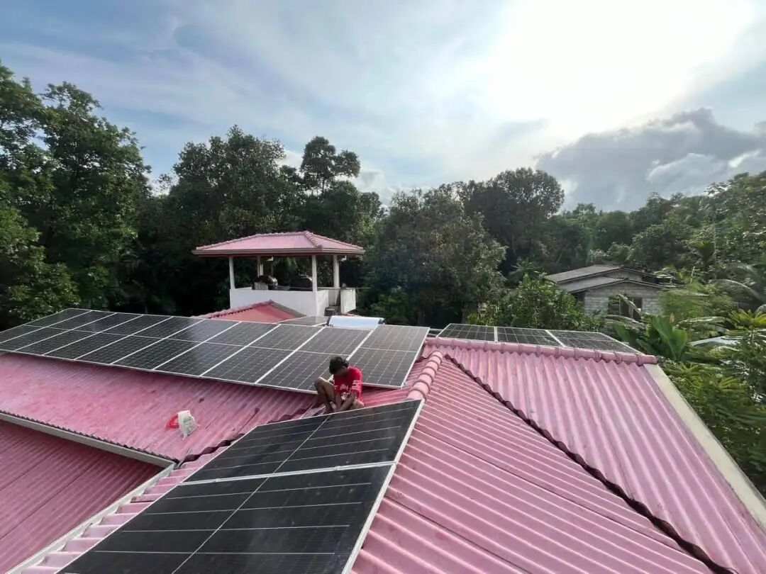
PV Panel Installation Photo
On-site Operating Conditions
The primary electrical load of this project is the three-phase grain huller with a rated power of 11 kW, running on 380 V three-phase alternating current. Processing activities mostly take place in daylight, and during peak harvest seasons, the equipment may run for 6 to 8 hours each day.
Deployment brought several tough practical challenges. First, the three-phase motor draws an enormous inrush current at startup, placing stringent demands on the instantaneous power delivery capability of the entire system. Insufficient power support will easily trigger protective shutdowns. Second, the local grid is poor in quality with erratic voltage and unpredictable outages. The system must achieve seamless switching between grid-tied and off-grid modes without interrupting machine operation.
In terms of production rhythm, photovoltaic power drives the equipment on sunny days. When cloudy weather arrives or sunlight fades towards dusk, the energy storage battery kicks in to maintain production. Moreover, considering local maintenance conditions in Africa, skilled technicians capable of intricate equipment servicing are scarce. Hence the whole system is designed for high integration, simple operation, remote status monitoring and minimal on-site commissioning.
The complete setup consists of a main inverter unit, an energy storage cabinet, a photovoltaic array and a full suite of auxiliary components. Details of the photovoltaic modules will not be elaborated here; the focus lies on the core hardware governing system operation. The system connects to the workshop’s original power distribution circuit, with the huller, on-site lighting and small auxiliary fans all connected to this shared AC busbar.
The daily operating logic is straightforward. Electricity generated by solar panels supplies the huller first, and surplus power is stored in the battery. As sunlight weakens and photovoltaic output falls short of load demand, the battery discharges to fill the gap. If the battery drains down to its cut-off threshold, the system automatically switches to mains power or a backup diesel generator, requiring no manual intervention at any stage.
Introduction to Core Equipment
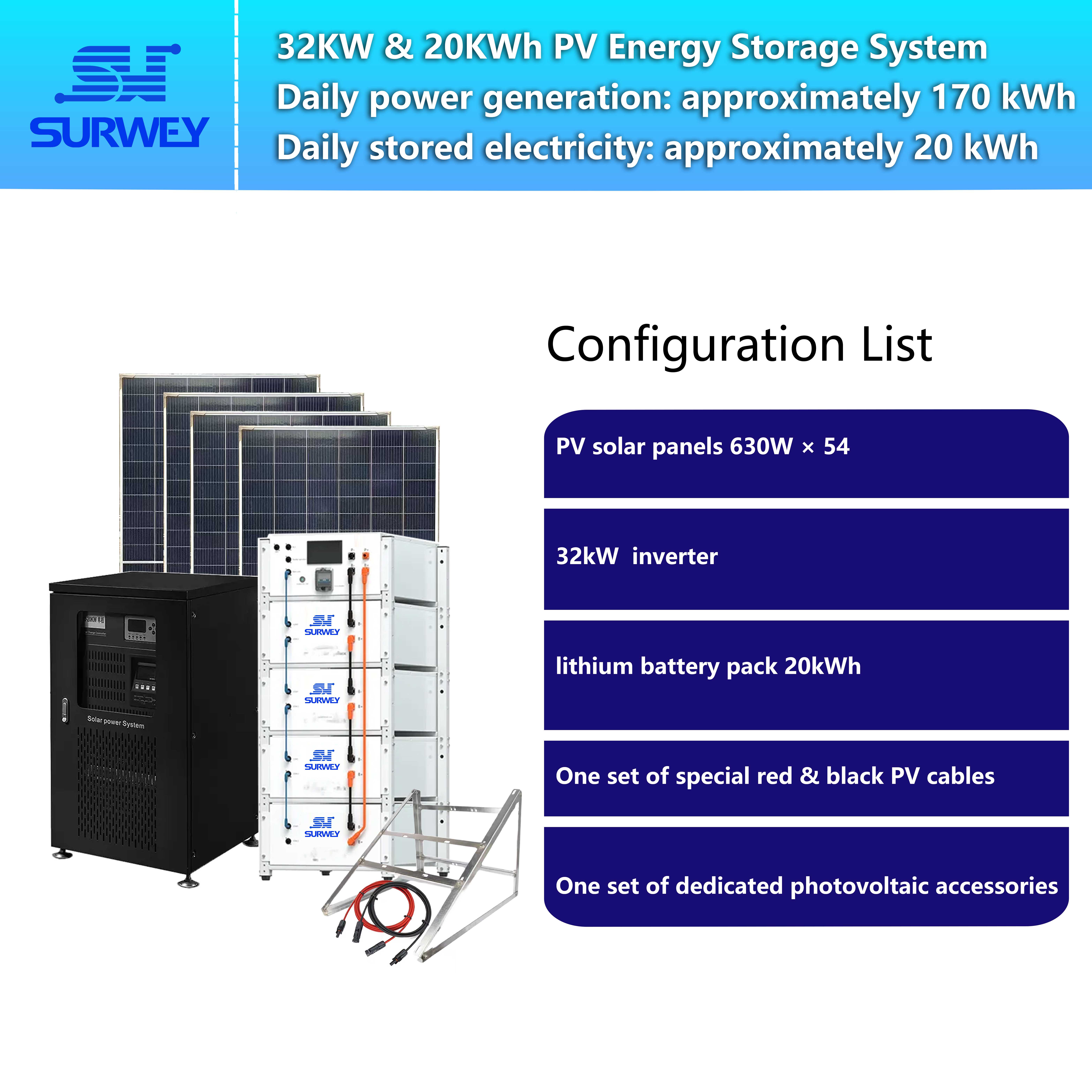
32 kW Three-Phase Hybrid Inverter — The Brain and Heart of the System
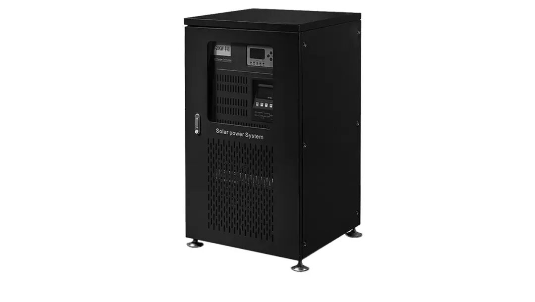
32 kW Three‑Phase Hybrid Inverter
The inverter stands as the most critical component of this solar-storage system, acting as the master dispatcher for this microgrid. Direct current from solar panels, stored battery power and unstable mains electricity all converge within this unit for unified regulation and conversion.
It converts direct current from photovoltaics and batteries into standard three-phase 380 V pure sine-wave alternating current suitable for the huller. The waveform is often overlooked, yet poor-quality power supplies with distorted waveforms cause excessive heating and noise during motor operation, gradually damaging windings over time. This inverter outputs clean pure sine waves, making it well suited for inductive industrial loads such as the huller motor.
It incorporates two independent MPPT solar tracking channels that operate without mutual interference, each searching separately for the maximum power point of its photovoltaic array. Even with unequal numbers of modules connected to the two channels, power generation efficiency will not be compromised — this forms the hardware foundation for our uneven string configuration adopted in this project. The inverter also supports parallel connection of multiple units. If the workshop expands later and load demand rises, an additional identical inverter can be added for capacity expansion instead of replacing the entire system, offering great upgrade flexibility.
Built to cope with the erratic African grid, it features millisecond-level seamless switching between grid-tied and off-grid modes. If the grid trips unexpectedly, the system shifts instantly to off-grid solar-storage operation so the huller keeps running. Once grid power recovers, it transitions smoothly back to grid-tied mode. Comprehensive onboard protection safeguards against overvoltage, overload, overheating and short circuits with automatic detection. A local LCD panel enables on-site parameter configuration, while remote communication allows operators far away to retrieve operational data including power generation, battery status and load power. Alerts are pushed for abnormalities, perfectly fitting remote sites with limited local technical staff.
20 kWh High-Voltage Energy Storage Cabinet — The Energy Reservoir for Production
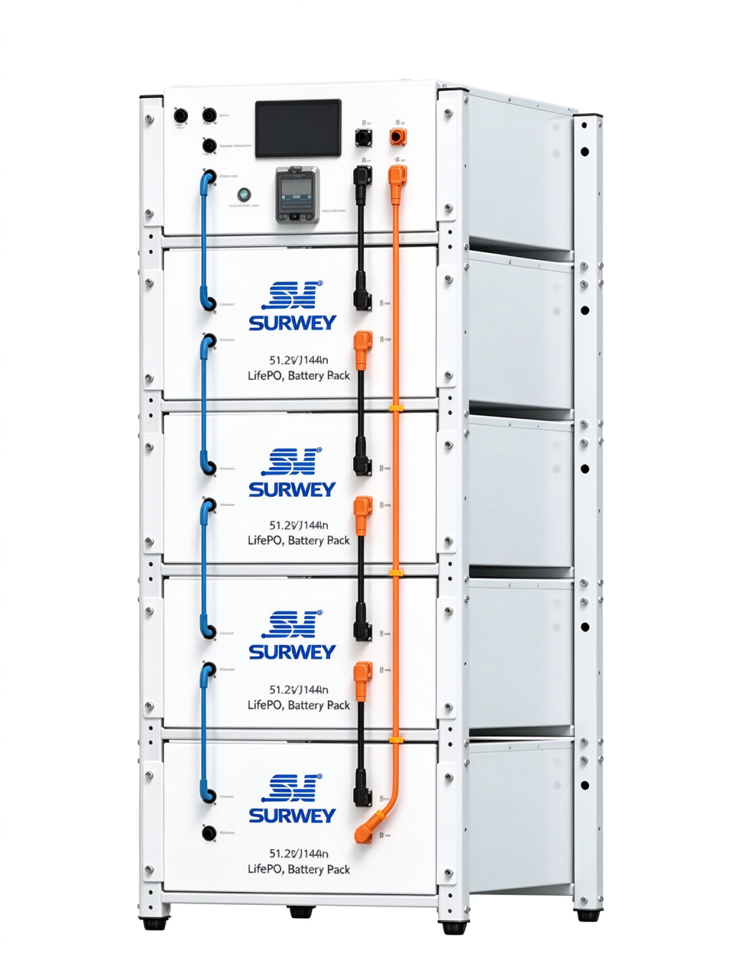
20 kWh High‑Voltage Energy Storage Cabinet
Power generation alone is not enough. The energy storage cabinet functions as the system’s reservoir, storing excess solar energy during the day and releasing power on cloudy days, at dusk or during blackouts to keep production uninterrupted.
This cabinet adopts lithium iron phosphate cells, which boast superior thermal stability, higher safety and long cycle life compared with other battery chemistries, ideal for repeated charging and discharging in commercial and industrial scenarios. It follows an integrated high-voltage cabinet design assembled from multiple battery modules, embedding a full BMS (Battery Management System). The BMS continuously monitors the voltage and temperature of every cell, performs automatic cell balancing and prevents overcharging and overdischarging. It issues alarms and activates protection automatically upon faults without constant manual supervision.
A major merit of the high-voltage architecture is lower operating current for the same power output, reducing cable heating and line losses. This eases on-site wiring work and lowers failure risks. Delivered as a fully integrated product, the cabinet requires no piecemeal battery assembly on site. It can be commissioned immediately once wired properly, with no dedicated battery room required. It only needs a well-ventilated, dry and shaded indoor corner in the workshop with proper grounding. Its modular design allows users to add matching battery modules later to boost energy capacity.
Auxiliary Components for Long-Term Stable Operation
Many system failures stem not from the main units but neglected small accessories. This project is equipped with dedicated PV DC cables, PV connectors, metal mounting racks and a solar charge controller.
The solar charge controller supports automatic recognition of 12 V / 24 V / 48 V battery voltages, with a peak MPPT tracking efficiency of up to 99%. It can raise energy yield by roughly 20% versus conventional PWM controllers. Independently managing photovoltaic charging and coordinating with the inverter for energy scheduling, it features an LCD display showing real-time PV and battery metrics. Its intelligent battery control logic supports multi-mode load output adaptable to diverse site conditions. Optional RS485 communication enables centralized monitoring, while appearance, colour schemes and operating parameters can be customised for off-grid storage applications.
DC cables are selected to withstand intense outdoor exposure, with excellent ageing and UV resistance to endure Africa’s high temperatures and strong sunlight. PV connectors serve as quick coupling elements for PV circuits, waterproof and dustproof to guarantee reliable DC connections outdoors and avoid loose contacts and overheating. Metal racks secure the photovoltaic array with sufficient structural strength to withstand local strong winds and hold modules firmly. Though seemingly insignificant, these accessories underpin reliable year-round system performance.
PV String Design Details
String configuration was validated according to the inverter voltage specifications and local low-temperature conditions. Each module has a voltage at maximum power point Vmp = 41.69 V and an open-circuit voltage Voc = 48.59 V. The inverter MPPT operating window ranges from 240 V to 360 V, with a maximum allowable open-circuit voltage of 450 V.
Six modules are connected in series per string:
- Operating voltage per string: 41.69 × 6 = 250.14 V, falling within the valid MPPT tracking range
- Open-circuit voltage per string: 48.59 × 6 = 291.54 V, well below the device voltage limit, retaining ample safety margin even when low temperatures at high altitudes lift module voltage.
Fifty-four modules are deployed in total. With six modules per string, nine PV branches are formed and assigned to the two independent MPPT channels: five strings (30 modules) to the first channel and four strings (24 modules) to the second, utilising all modules.
Construction specifications mandate identical module counts for all strings connected to a single MPPT channel. Mismatched branch voltages would induce circulating current, dragging down generation efficiency or even damaging components. Since the two MPPT channels operate independently, differing string counts between them do not impair performance. During cabling, AC and DC lines are routed separately, DC cable runs are shortened, and shading on modules is avoided. After wiring, the open-circuit voltage of each string is measured one by one; branches are connected to the inverter only once voltage deviations meet acceptance criteria.
How the System Drives the 11 kW Huller Reliably
Video of System Operating Principle
A frequent concern raised by clients is whether solar-storage systems can handle the large inrush current when starting motor-type impulse loads — this lies at the heart of the project design.
First, the inverter has a rated capacity of 32 kW, offering abundant power headroom against the 11 kW huller. Even with additional small loads such as lighting and auxiliary fans running simultaneously, the overall load factor remains within a safe band. The inverter supports short-time overload capability. Paired with high-rate discharge from the energy storage cabinet, the DC bus voltage stays firmly stabilised at motor startup, preventing low-voltage protective shutdown triggered by transient heavy current.
The high-quality pure sine-wave AC output is gentle to motor windings and avoids extra heat and noise. Millisecond-scale grid-tie / off-grid switching ensures that if local power cuts out, the system instantly switches to solar plus battery supply, so the huller experiences virtually no power interruption. It transitions back smoothly once grid supply resumes.
Even with generous hardware margins, on-site installation of a soft starter at the motor terminal is recommended. It further suppresses the starting inrush current, protecting the huller motor itself while reducing impulse stress on the inverter and extending the service life of the whole solar-storage setup.
Daily Power Demand and Energy Matching Calculation
The main load is the 11 kW three-phase huller. Based on local processing habits, effective daily production is assumed to last seven hours. Since the load does not run continuously at full power, the estimated average daily consumption is approximately 65 kWh. The photovoltaic array generates power through daylight hours, prioritising the huller and charging the battery with surplus electricity. The usable capacity of the energy storage cabinet is around 16.4 kWh, covering power shortfalls during weak sunlight, dusk and brief blackouts.
When sunlight is strong, PV output fully satisfies the huller’s full-load demand while continuously recharging the battery. As illumination fades and PV output drops below load consumption, the storage battery discharges automatically to bridge the gap. Once the battery hits its protection cut-off level, the system switches over to mains power or a backup diesel generator as the final safeguard. With no production scheduled overnight, the system enters low-power standby mode, sustaining only communication and monitoring until sunrise the next day.
Postscript
For this grain milling workshop in Ethiopia, this solar-storage system represents far more than a simple assembly of hardware. It resolves a genuine existential challenge: owners no longer fear sudden blackouts halting production, and they need not watch grain spoil from moisture caused by idle machinery in harvest season. Production is finally freed from the constraints of an unreliable local grid.
In many overseas regions with underdeveloped power infrastructure, photovoltaic energy storage is no longer a luxury add-on but fundamental infrastructure keeping small industries operational. A successful solar-storage project is not defined by flashy parameter specifications. It hinges on thoughtful detail engineering tailored to local irradiation conditions and load characteristics, delivering hardware that can be practically deployed and reliably sustain end users’ production.


