
Bid Farewell to Frequent Power Outages: A New On‑Site Hybrid Solar‑Storage Solution for Overseas Residential Use Adapted to Extreme Temperature Fluctuations
1 Project Overview
1.1 Project Location
This project is situated in the suburbs of Guadalajara, Jalisco, Mexico, for a two‑story self‑built residential house with a flat concrete roof suitable for rooftop photovoltaic installation. The local peak sunshine duration is approximately 5 hours, offering favorable solar irradiance. The regional power grid features ageing infrastructure, and power outages frequently occur during thunderstorms in the rainy season and peak electricity consumption in summer, resulting in poor power supply reliability.

PV module installation photo
1.2 End‑User Profile
The household consists of four members, equipped with a full set of common domestic electrical appliances. Key loads include a side‑by‑side refrigerator, whole‑house LED lighting, WiFi communication equipment, a living‑room television, a floor‑standing air conditioner for the living room, a wall‑mounted air conditioner for the master bedroom, a washing machine, a domestic water booster pump, and various small charging devices.
1.3 Core User Requirements
- Harness abundant local solar energy to realize self‑consumption of photovoltaic power and reduce reliance on utility grid power.
- Deliver backup power supply during grid failures to maintain uninterrupted operation of the refrigerator, network and basic lighting, with priority given to emergency power for the master bedroom air conditioner.
- Adapt equipment layout to the available rooftop area; ensure safe and stable operation under the large diurnal temperature swings prevalent in the local region of Mexico.
- Support system monitoring for real‑time viewing of power generation and energy storage status, while reserving certain capacity for future expansion.
2 Overall System Configuration
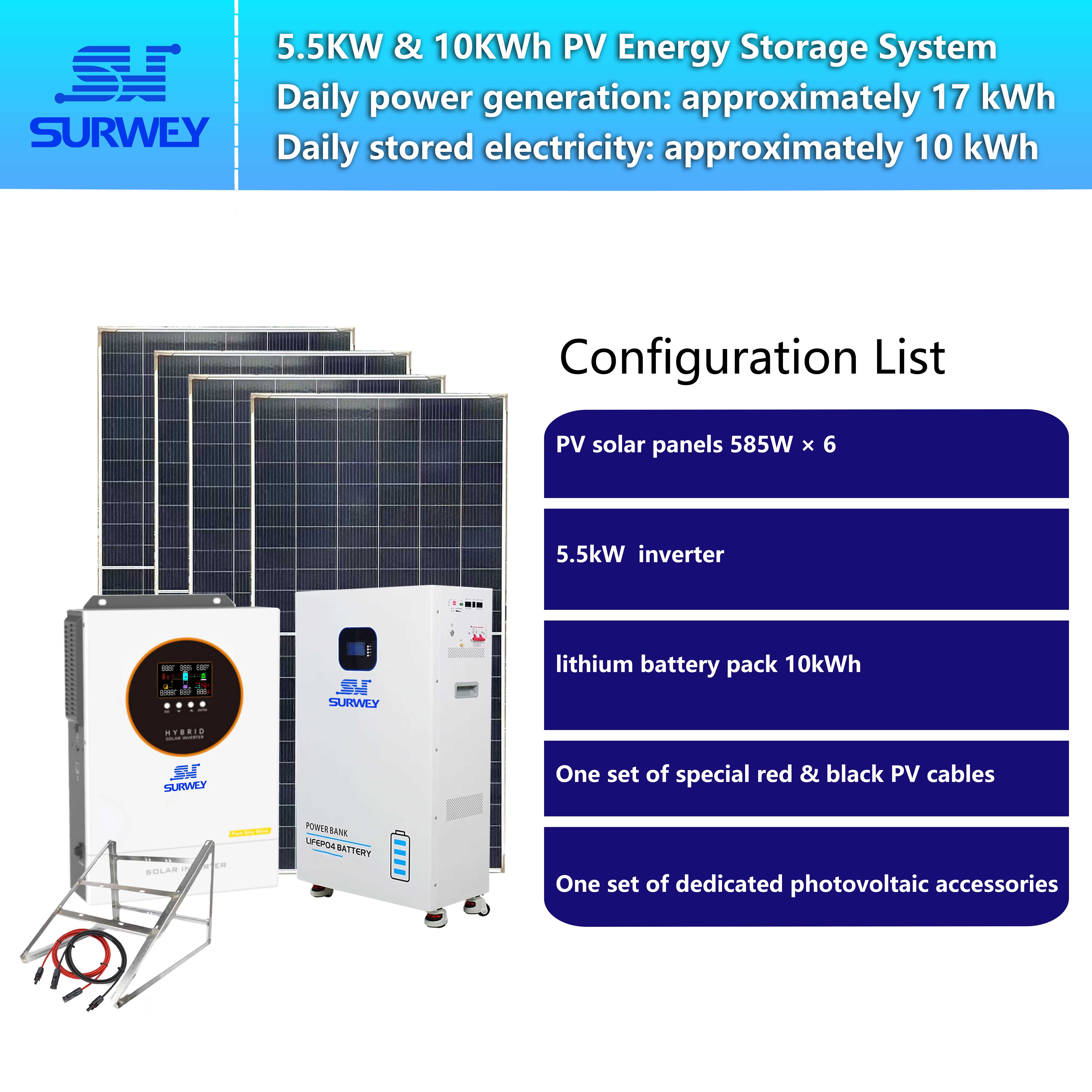
This project adopts a US‑standard single‑phase hybrid grid‑tied solar‑storage system, composed of photovoltaic modules, a hybrid grid‑tied energy storage inverter, lithium iron phosphate energy storage batteries, photovoltaic mounting brackets, DC cables and auxiliary accessories. The total installed photovoltaic capacity of the system is 3,510 W, the rated inverter power is 5.5 kW, and the energy storage battery capacity is 10.24 kWh.
| No. | Equipment Name | Specifications | Quantity | Remarks |
|---|---|---|---|---|
| 1 | Monocrystalline PV Module | 585 W, open‑circuit voltage: 51.66 V | 6 pcs | Flat rooftop mounting |
| 2 | Hybrid Grid‑Tied Energy Storage Inverter | Rated power: 5.5 kW, US standard 120 V / 240 V output, 48 V DC battery platform | 1 unit | Wall‑mounted on interior garage wall |
| 3 | Lithium Iron Phosphate Energy Storage Battery | Capacity: 10.24 kWh, 48 V platform, supporting BMS communication | 1 unit | Indoor wall‑mounted energy storage unit |
| 4 | PV Array Bracket | Fixed aluminium bracket for flat roof | 1 set | Fastened to concrete roof with chemical anchors |
| 5 | PV DC Cable | 4 mm² special PV DC cable | As required | Interconnection between rooftop and inverter |
| 6 | Installation Auxiliary Materials | Fuses, connectors, waterproof kits, etc. | 1 set | Supporting installation components for the system |
3 Product Introduction
3.1 Hybrid Grid‑Tied Energy Storage Inverter

US‑standard single‑phase 5.5 kW hybrid grid‑tied energy storage inverter
This US‑standard single‑phase 5.5 kW hybrid grid‑tied energy storage inverter adopts a 48 V battery voltage platform, compatible with the 120 V / 240 V domestic power standard in Mexico. Its MPPT operating voltage window ranges from 70 VDC to 280 VDC. It supports millisecond‑scale off‑grid switching upon power failure and enables automatic energy dispatching among photovoltaic generation, energy storage battery and utility grid. It features BMS communication interface and a built‑in WiFi module for remote monitoring of power generation, load and battery operating status. Capable of enduring high ambient temperatures, it serves as the core control unit for self‑consumption and emergency power supply of this solar‑storage system.
3.2 Lithium Iron Phosphate Energy Storage Battery, 10.24 kWh Wall‑Mounted

10.24 kWh wall‑mounted lithium iron phosphate energy storage battery
The selected 10.24 kWh wall‑mounted lithium iron phosphate energy storage battery operates on a 48 V voltage platform and supports bidirectional BMS communication and coordination with the inverter. Its cells achieve a cycle life exceeding 3,000 times, with multi‑level built‑in protection against overvoltage, undervoltage, overcurrent, overtemperature and short circuit. The wall‑mounted design saves indoor floor space. It stores surplus photovoltaic power for household loads at night and delivers backup power together with the inverter during grid outages, satisfying long‑duration power supply for essential domestic loads.
3.3 Monocrystalline Photovoltaic Module

The 585 W half‑cut monocrystalline PV modules selected feature stable power generation across a wide operating temperature range of ‑40 ℃ to +85 ℃. Six modules are deployed in this project, wired as two parallel strings with three modules in series per string. Verified under high and low temperature conditions, the output voltage and current perfectly match the inverter’s MPPT operating window. These modules convert sunlight into direct current as the primary energy source of the whole system: generated power supplies household loads preferentially during daytime, and excess power is stored in the energy storage battery.
4 Electrical Design and Verification of PV Strings
4.1 String Layout Scheme
Six pieces of 585 W modules are configured into two parallel branches, each containing three modules connected in series and connected to the inverter MPPT port. All series branches carry identical module counts to minimise mismatch losses.
Key electrical parameters under STC:
- One series string of three modules: Voc = 154.98 V; Vmp = 128.49 V; Imp = 13.86 A; Isc = 14.44 A
- After parallel connection of two strings: total Imp = 27.72 A, total Isc = 28.88 A
- Total system power under STC: 3,510 W
4.2 Voltage Verification under Extreme Operating Conditions
Given the large diurnal temperature variation at the project site, the lowest nighttime temperature in winter can reach ‑10 ℃ while the module operating cell temperature can rise to +45 ℃ in summer. It is necessary to verify whether the voltage under extreme temperatures stays within the allowable range of the inverter.
- Open‑circuit voltage verification at ‑10 ℃: Open‑circuit voltage rises at low temperatures. After correction using the temperature coefficient, the open‑circuit voltage of the full string at ‑10 ℃ is approximately 168.8 V. The maximum tolerable PV‑side open‑circuit voltage of the inverter is 300 V; 168.8 V is well below this upper limit with no risk of overvoltage breakdown.
- Operating voltage verification at +45 ℃: Operating voltage drops under high temperatures. The corrected Vmp under high‑temperature conditions is roughly 118 V, which exceeds the minimum MPPT operating voltage of 70 V. The operating voltage remains within the valid MPPT tracking range, eliminating the risk of MPPT dropout and generation failure under high heat.
4.3 Input Current Verification
The maximum operating current of the two parallel strings is 27.72 A and the maximum short‑circuit current is 28.88 A, both far below the inverter’s upper PV input current limit of 100 A. Sufficient safety margins are reserved for DC cables, fuses and terminals, ensuring the electrical circuit complies with safety regulations.
Conclusion for string design: The configuration of three modules in series and two strings in parallel is fully compatible with the electrical window of the 5.5 kW hybrid inverter for this project. It avoids overvoltage at low temperatures and MPPT dropout at high temperatures, meeting equipment specifications and local climatic requirements.
5 Power Generation and Load Matching Calculation
Video of system operating principle
Calculated theoretically based on the local effective peak sunshine of 5 hours: Theoretical daily generation = 3,510 W × 5 h = 17.5 kWh. Taking conversion loss of the inverter, cable loss, module temperature attenuation, dust accumulation and shading into account, an overall efficiency factor of 0.8 is adopted. The actual average daily output of the system reaches approximately 14 kWh.
Load matching analysis:
- Daytime: Basic daytime loads (refrigerator, lighting, network, small household appliances) consume around 4–5 kWh. Photovoltaic power supplies the loads directly on priority, and surplus power charges the battery.
- Evening to nighttime: Loads draw power preferentially from the stored energy in the battery. Once the battery reaches the discharge cut‑off threshold, the system automatically switches to utility grid power.
- Emergency operation during power outage: The system switches to off‑grid mode within milliseconds with combined photovoltaic and battery power, sustaining continuous operation of the refrigerator, network and lighting, and supporting prolonged emergency use of the master bedroom air conditioner.
- Energy logic: PV power supplies loads directly → surplus power charges the battery → excess power after the battery is fully charged can be fed into the utility grid.
The usable capacity of the 10.24 kWh energy storage battery can sustain essential household loads for 6–8 consecutive hours, satisfying the emergency power target.
6 Key Points for On‑Site Installation
- PV bracket installation: Fixed aluminium brackets are adopted with inclination matched to the local latitude. Base plates are anchored to the concrete roof using chemical anchors together with waterproof sealing processes to prevent roof leakage.
- DC wiring: Special 4 mm² PV DC cables are selected with routing optimised to control cable length and line loss. Each string is equipped with fuses of appropriate rating, and all joints are fully waterproofed.
- Inverter installation: Wall‑mounted on an interior garage wall away from direct sunlight. Clearance is reserved around the unit for air‑cooled heat dissipation. Short wiring runs between the inverter and battery reduce voltage drop on the 48 V DC loop.
- Energy storage battery installation: Mounted on load‑bearing walls with reinforced fasteners and reserved access space for maintenance. Complete communication wiring is implemented to realise BMS coordinated charge and discharge management.
- System parameter commissioning: Set to self‑consumption priority mode. Charge and discharge protection thresholds for the battery are configured, and the WiFi monitoring function is activated for remote access to generation metrics and battery SOC status.
7 Evaluation after Trial Operation
Following installation and commissioning, the system underwent two weeks of on‑site trial operation, with results summarised below:
- Power outage switching: Millisecond mode switching is achieved; the refrigerator and network equipment run continuously without perceptible interruption, fulfilling the core requirement of backup power supply.
- Charge and discharge performance: Photovoltaic power feeds loads preferentially during daytime and starts charging the battery in the early afternoon, which is mostly fully charged by dusk. Power drawn from the battery supports household consumption at night, and the battery delivers the expected endurance when the master bedroom air conditioner is turned on for emergency cooling in summer.
- Monitoring function: Remote viewing of module voltage and current, battery state of charge and daily generation data is available for visualised status management.
- Climate adaptability: Under alternating high daytime and low nighttime temperatures, the inverter maintains stable MPPT tracking without overvoltage events or unexpected shutdowns. The safety margin of the string electrical design is validated in practical operation.
8 Project Summary and Insights
This residential solar‑storage solution consisting of a 5.5 kW hybrid inverter, a 10.24 kWh energy storage unit and 3,510 W of PV modules precisely accommodates the rooftop constraints, electricity consumption habits and backup power demands of the Mexican household without over‑specifying hardware.
For overseas residential solar‑storage projects, string voltage verification constitutes a core technical procedure. It is mandatory to fully consider the impact of extreme high and low ambient temperatures on module voltage to avoid low‑temperature overvoltage and high‑temperature MPPT dropout faults. The string scheme of three modules in series and two strings in parallel in this project has been validated through theoretical calculation and field operation and can serve as a valuable reference.
A large number of residences across Latin America suffer from unstable grid power supply, driving sustained market demand for residential solar‑storage systems. Successful deployment requires attention not only to equipment selection but also to on‑site execution details including bracket waterproofing, cable specification, battery mounting reinforcement and charge‑discharge strategy tuning to guarantee long‑term stable system performance.
The configuration philosophy and electrical verification methodology of this project can be adopted as a technical reference for other residential solar‑storage projects located at similar latitudes and under comparable climatic conditions.


