
Technical Proposal Report for the 3 MWp Hybrid Solar-Storage Integrated Project at a Polypropylene Production Plant on the Brazilian Plateau
1 Project Overview
This project is located on the Brazilian Plateau and serves a polypropylene chemical production plant, with a 3 MWp hybrid grid solar-storage integrated system to be constructed. The power consumption of core compression, extrusion and post-treatment processes of the polypropylene production unit is concentrated during day-shift production hours. At night, only basic low-load equipment such as circulation pumps, safety systems and cooling systems remain in operation while the main production line runs under reduced load. Such load characteristics highly match the strong daytime solar resources on the plateau.
The project adopts the technical route of photovoltaic (PV) modules + containerized energy storage + hybrid grid inverters, implementing a three-tier energy utilization mode: self-consumption with priority, storage of surplus electricity in energy storage batteries, and grid feed-in once the energy storage system is fully charged. Idle open space within the plant site serves as the main area for PV arrays, while factory rooftops are used for supplementary installation. Relying on the existing transformers of the plant, the system connects to the grid on the low-voltage side without additional step-up cabins. In view of the risks posed by flammable media and dust in polypropylene chemical production, special designs for explosion protection, anti-static measures and fire isolation are incorporated to ensure the safety of solar-storage facilities and chemical production units. All 4,616 pieces of 650 W PV modules will be fully deployed.

PV Module Installation Drawing
2 On-site Basic Conditions of the Polypropylene Plant
2.1 Site Conditions
- Ground-mounted PV Arrays: Approximately 30,000 m² of available open land inside the plant is designated for the main PV layout. The site is kept away from explosion hazardous zones such as polymerization reaction areas and propylene storage tank farms, complying with chemical safety spacing requirements. It can accommodate mounting brackets, inverters and energy storage containers, with reserved access for maintenance and fire fighting.
- Rooftop Supplementary PV Installation: About 2,000 m² of usable rooftop area is available, limited to roofs of buildings outside explosion hazardous zones. Ballasted mounting is adopted to avoid damage to roof waterproofing. PV equipment is strictly prohibited on rooftops of process unit areas and powder processing workshops.
2.2 Power Grid and Transformer Conditions
- Rated capacity of existing plant transformer: 1,200 kW
- Grid connection method: An outdoor prefabricated step-up cabin will be added. Surplus power generated by the solar-storage system will be stepped up and connected to the public distribution network at medium voltage.
- The power grid supports bidirectional metering for surplus electricity feed-in. The plant’s power distribution system complies with chemical-grade standards and is equipped with a complete earthing and protection system.
2.3 Power Load Profile of the Polypropylene Plant
- Operating Conditions: The polypropylene unit completes high-energy-consuming processes including extrusion granulation, material conveying and circulating compression during day shifts. At night, main production processes are shut down under reduced load, and only basic safety loads such as cooling systems, circulating water pumps and safety monitoring devices remain operational. This creates a pattern of concentrated high power consumption in daytime and low base load at night.
- Power Consumption Data: The plant maintains a stable monthly power consumption of over 180,000 kWh, equivalent to an annual electricity consumption of approximately 2.16 million kWh. Major power consumers include circulating gas compressors, extrusion granulators, material conveying fans and cooling water pumps. Short-term impact fluctuations exist in the load.
2.4 System Design Objectives
- Leverage solar resources on the Brazilian Plateau to reduce purchased industrial power for the polypropylene plant and raise the self-sufficiency rate of on-site electricity.
- Use energy storage to smooth power surges caused by start-stop cycles of compressors and extruders, and absorb excess midday PV power.
- The hybrid grid architecture can supply emergency power to critical safety loads of the plant (circulating cooling, instrument power supply) in case of grid abnormalities.
- Fully deploy all 4,616 pieces of 650 W modules while balancing system efficiency and site boundary constraints.
- Strictly follow requirements for explosion protection, fire prevention, anti-static control and safety spacing for chemical plants, with physical isolation between solar-storage facilities and polypropylene production units.
3 Overall System Configuration
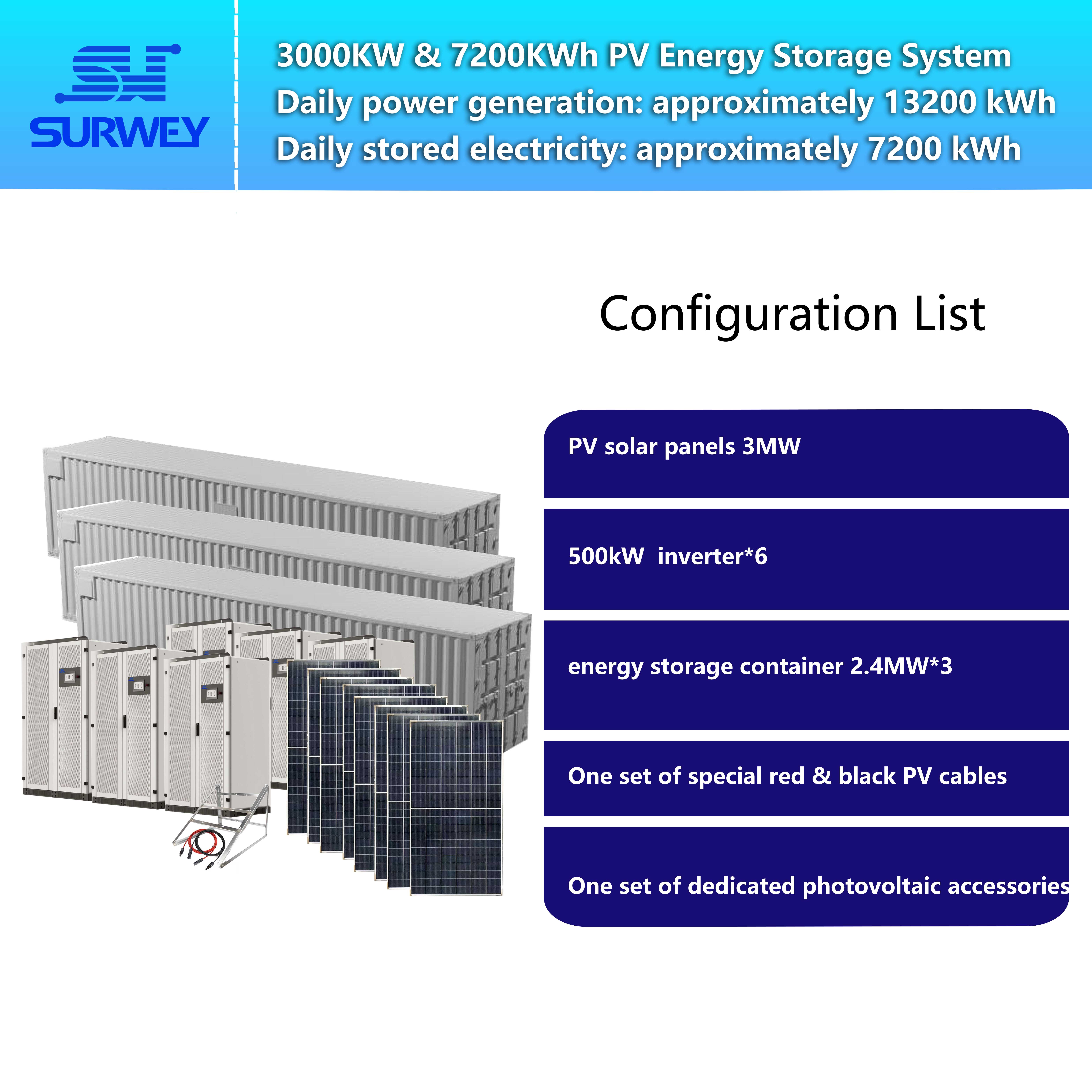
4 Technical Specifications of Key Equipment
4.1 PV Modules
High-power 650 W N-type monocrystalline PV modules are selected, adapted to the high altitude, strong ultraviolet radiation and large diurnal temperature variation on the Brazilian Plateau.
- Cell layout: 132 cells (6 × 22), N-type monocrystalline
- Peak power: 650 W
- Voltage at maximum power point: approx. 42 V
- Open-circuit voltage: approx. 49.7 V
- Maximum DC voltage of the system: 1,500 V DC
- Operating temperature range: −40℃ ~ +85℃
- Product features: low degradation rate and excellent low-light power generation performance. Module frames and the bracket system are fully equipped with anti-static earthing to meet anti-static requirements for chemical plants.
4.2 500 kW Hybrid Grid Inverter

As the core power conversion device of the solar-storage system, the inverter is installed outside explosion hazardous zones. It supports grid-tied and off-grid hybrid operation and integrates a static transfer switch (STS) for fast switching. When the grid fails, it can provide uninterrupted power supply for critical safety loads of the polypropylene plant, such as instruments and circulating cooling equipment.
- Rated AC output power per unit: 500 kW
- Rated AC voltage: 400 V; operating voltage range: 320–460 V
- Maximum DC input voltage on the PV side: 1,000 V; MPPT operating voltage: 250–850 V
- Operating voltage range on the battery side: 500–850 V
- Multiple units can be paralleled and connected to the EMS for coordinated dispatching among PV generation, energy storage, chemical impact loads and the utility grid.
- Supports three-phase unbalanced output to accommodate load fluctuations caused by start-stop of compressors and extruders. It adopts air cooling, with an ingress protection rating of IP20. The equipment enclosure is reliably earthed, and surge protection is installed for signal circuits to withstand lightning surges common on plateaus.
4.3 40 ft Containerized Energy Storage System (2.411 MWh)

2.411 MWh 40 ft Containerized Energy Storage System
This prefabricated integrated 40 ft containerized energy storage unit integrates lithium iron phosphate battery clusters, BMS, fire protection, temperature control and monitoring modules, eliminating the need for a dedicated battery room.
- Rated energy of single cabinet: 2.411 MWh; battery chemistry: lithium iron phosphate
- Rated voltage: 768 V; operating voltage range: 672–864 V
- Comprehensive system efficiency: 96%; allowable depth of discharge: 90%
- Charge/discharge rate: 0.5 C for charging; 0.5 C–1 C for discharging
- Equipped with smoke detection, temperature control and automatic fire suppression systems inside the container. The container shell is treated for anti-corrosion and anti-static earthing.
- Communication protocols: CANBUS, Modbus TCP/IP, for connection to the upper EMS platform
- Design service life: ≥ 15 years
- The container is sited away from polypropylene process units and storage tank farms to satisfy chemical fire safety spacing requirements.
5 PV String Design and Module Allocation
5.1 Basis for String Configuration
Brazil features mild extreme low temperatures at low elevations, so the increase in module open-circuit voltage under low temperature remains controllable. Considering the 1,000 V DC upper limit of the inverter and the MPPT window, two string specifications are adopted:
- Standard string: 17 modules per string Power per string: 17 × 650 W = 11,050 W (11.05 kW), for ground-mounted PV arrays
- Short string: 9 modules per string Power per string: 9 × 650 W = 5,850 W (5.85 kW), only for constrained corner rooftop locations within safe zones. Short strings and all PV modules are forbidden in process hazardous zones.
For one single 500 kW inverter, the maximum number of connectable standard strings (17 modules each) is approximately 45: 500 kW ÷ 11.05 kW ≈ 45 strings.
5.2 String and Module Allocation for Inverters
All 4,616 modules of the project are fully utilized across six inverters according to the following allocation:
- Inverters No. 1–4: Each connects 45 standard strings of 17 modules, with 765 modules per unit; DC connected power: approx. 497 kW
- Inverter No. 5: 45 standard strings of 17 modules + 1 short string of 9 modules, totaling 774 modules; DC connected power: approx. 503 kW
- Inverter No. 6: 46 standard strings of 17 modules, totaling 782 modules; DC connected power: approx. 508 kW
Module verification: 765 × 4 + 774 + 782 = 4,616 modules, with no idle modules.
Note: The DC side of Inverters No. 5 and No. 6 slightly exceeds the AC rated capacity of 500 kW, which represents conventional DC over-sizing in the industry. The inverters will automatically limit output at the AC cap to make full use of plateau solar irradiance. Short strings occupy independent MPPT branches separately. Most branches adopt uniform standard strings of 17 modules for high voltage consistency, facilitating troubleshooting and maintenance at the chemical plant site.
6 PV Array Layout and Safety Arrangement for Chemical Scenarios
6.1 Ground-mounted PV Arrays (Main Installation)
The 30,000 m² open land inside the plant is selected for layout, maintaining fire safety distances from polypropylene polymerization units, propylene storage tanks and powder granulation workshops and avoiding explosion hazardous zones. After reserving space for energy storage stations, fire lanes and maintenance passages, the site can accommodate the 3 MWp installation.
- Array orientation: Located in the Southern Hemisphere, PV modules face due north.
- Bracket type: Fixed hot-dip galvanized brackets installed at the optimal tilt angle calculated based on local latitude. The whole bracket system is equipped with equipotential anti-static earthing to mitigate static risks in chemical environments.
- Array spacing: Sufficient spacing between front and back rows to avoid shading.
- Cable routing: Flame-retardant DC cables are laid along metal cable trays with reliable earthing. Cables are routed away from process pipelines and flammable medium trenches and connected to inverters installed in safe zones as close as possible.
- Zoning planning: The arrays are divided into separate zones with reserved passages for equipment transportation and personnel maintenance. Energy storage containers and inverters are centrally placed on a safe plot close to the plant power distribution room and kept away from chemical process units.
7 System Operation and Control Logic
Video of System Operating Principle
The Energy Management System (EMS) centrally controls the entire hybrid grid solar-storage system. In response to the plant’s operational profile featuring high daytime load and low nighttime safety load, a three-level control strategy is implemented:
Level 1: On-site self-consumption of PV power (day-shift production) Generated PV power is prioritized to supply production loads such as extrusion, compression and material conveying of the polypropylene plant for local consumption, reducing power purchased from the grid. For instantaneous impact loads caused by compressor start-stop, energy storage responds rapidly to smooth power fluctuations and reduce disturbances to the plant power network.
Level 2: Charging with surplus electricity At midday with peak solar irradiance, if PV output exceeds the real-time production load of the plant and the energy storage system is not fully charged, surplus power will be stored in the energy storage system. When the polypropylene line shuts down briefly for midday breaks, all PV power charges the energy storage system to avoid massive reverse power flow into the transformer.
Level 3: Grid feed-in of surplus power upon full charging If high PV output continues and the energy storage system reaches full state of charge, excess electricity will be fed into the utility grid.
Time-sequence supplement: As solar irradiance declines in the afternoon and PV output can no longer satisfy the power demand of the polypropylene unit, stored energy will be discharged to continue supplying production loads.
Nighttime operating conditions: The main production of the polypropylene plant runs under reduced load, and only basic safety loads including cooling and instruments remain active. Power supply is prioritized from the grid. The energy storage system normally does not discharge actively and retains reserved emergency capacity.
Island mode under grid failure: Hybrid grid inverters switch to island operation. PV and energy storage jointly supply power preferentially to critical safety loads such as the plant’s instrument system and circulating cooling system to enable safe shutdown of the chemical unit and prevent secondary process safety incidents.
Important note: Island mode only powers critical safety loads and cannot drive main production equipment such as large compressors and extruders.
8 Summary of Design
This proposal is customised for the unique operating conditions of the polypropylene chemical plant in Brazil rather than a generic solar-storage template.
In terms of string allocation, all modules are fully utilised within the power limits of inverters. The design accommodates both large-area ground layout and irregular rooftop spots. Moderate DC over-sizing maximises revenue from high plateau irradiance while keeping maintenance complexity under control.
For grid connection, instead of adopting the conventional scheme of adding step-up cabins, the design builds on the plant’s existing power assets. Software-based coordinated control between EMS and energy storage addresses transformer capacity constraints, reducing civil work, approval and construction workloads and easing pain points for overseas project delivery.
Besides peak shaving and valley filling for electricity consumption, the load-oriented design also smooths impact loads generated by frequent start-stop of large chemical equipment. The island function is not intended for main production machines but focuses on safety loads required for safe shutdown of chemical units, avoiding process secondary risks triggered by power outages.
From the safety perspective, equipment siting and isolation follow the zoning of chemical explosion hazardous areas. Earthing, flame retardancy and fire protection of the solar-storage system are integrated into the plant’s original chemical safety regime to satisfy special constraints for environments with flammable media and dust.
Beyond electricity savings, the complete system improves power supply stability for the plant. It forms a feasible implementable solution subject to multiple boundary constraints including local solar resources, site conditions, grid requirements and chemical safety standards.


