
Dry Season Power Generation, Wet Season Power Assurance|Technical Analysis of Residential PV-ESS System for Single-Family Homes in Thailand
1. Project Overview
1.1 Project Location
The project is situated in Thailand within a tropical monsoon climate zone. The region boasts abundant solar irradiance year-round, divided into wet and dry seasons, with generally high ambient temperatures and a wide annual temperature span. Solar resources are excellent in the dry season, while continuous overcast days and short-duration rainfall frequently occur in the wet season. The local power grid suffers from voltage fluctuations and occasional short outages, threatening the power supply stability of critical household loads.

PV Module Installation Drawing
1.2 Project Positioning
This is a grid-tied residential integrated photovoltaic and energy storage system. It captures solar energy via rooftop PV modules and adopts an all-in-one hybrid inverter to realize power conversion, energy storage and load supply. The system supports self-consumption of on-site solar generation, surplus energy storage and backup power during grid failures. It prioritizes meeting household electricity demand, enhances energy independence and copes with unstable grid conditions.
1.3 Overall System Configuration
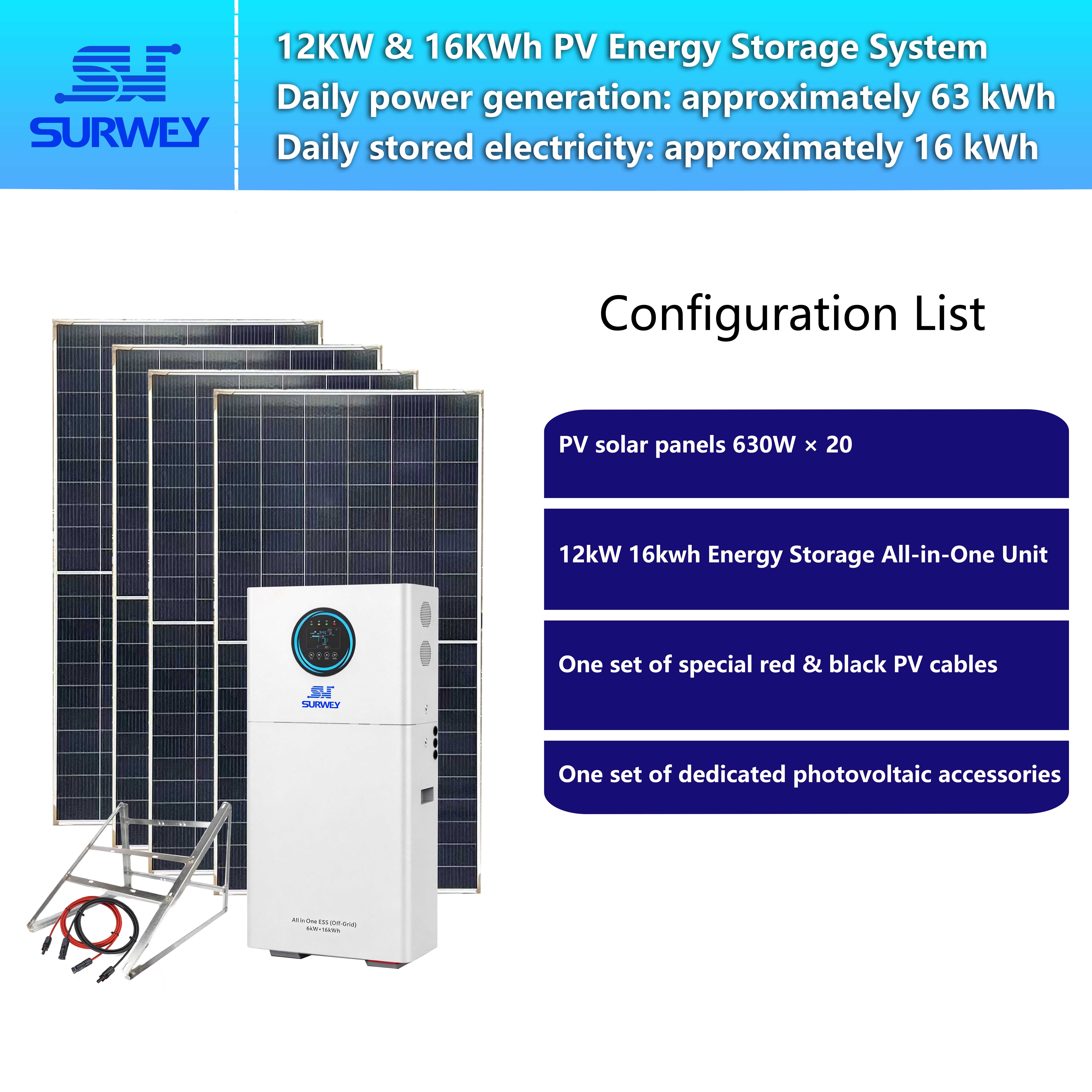
The core equipment adopted is a 12 kW / 16 kWh hybrid inverter and energy storage all-in-one unit. Its MPPT operating voltage window for PV input ranges from 80 V to 500 V, with a maximum PV input power of 15 kW. It is paired with N-type monocrystalline 630 W PV modules, with a total quantity of 20 modules. For string design, ten modules are connected in series to form one string, and two such strings are paralleled before connecting to the PV terminals of the inverter. The total installed capacity of the PV array reaches 12,600 W. With a battery depth of discharge limited to 90%, the usable energy capacity of the storage battery is 14.4 kWh.
2. Key Equipment Specifications
2.1 Hybrid Inverter & Energy Storage All‑in‑One Unit

12kW/16kWh Hybrid Inverter & Energy Storage All‑in‑One Unit
This integrated unit incorporates a PV MPPT charger, bidirectional inverter, BMS and control module in a compact enclosure, reducing on-site wiring workload and making it well suited for residential applications.
- PV-side Characteristics: Equipped with a wide-voltage MPPT controller supporting a broad PV input voltage range of 80–500 V, compatible with various series configurations. It features automatic maximum power point tracking to improve solar utilization, supports parallel connection of multiple PV strings, and integrates protection against overvoltage, overcurrent and reverse polarity.
- Battery Management: The built-in BMS is compatible with lithium and lead-acid batteries. It monitors battery voltage, current and temperature in real time, balances cell status and sets charge/discharge cut-off thresholds to prevent damage from overcharging or overdischarging.
- Inverter Output: It delivers a rated AC output of 12 kW with short-time overload capability to handle inrush loads such as air-conditioning compressors. Seamless switching between grid-tied and off-grid backup modes enables uninterrupted power supply to loads during grid faults.
- Monitoring & Communication: A wireless monitoring module is embedded for remote access. Users can view real-time data including PV output power, battery state of charge, household load consumption and system operating mode to facilitate maintenance and troubleshooting.
- Environmental Adaptability: The unit operates within an ambient temperature range of -10 °C to 50 °C with an IP20 protection rating. It shall be installed indoors in a shaded, rainproof equipment room away from direct sunlight and splashing water.
2.2 PV Modules
N-type monocrystalline 630 W PV modules are deployed for the project. They feature favourable temperature coefficients and low-light performance, adapting to high tropical temperatures. Key electrical parameters under STC (Standard Test Conditions, 25 °C) are listed below:
- Peak Power (Pmax): 630 W
- Open-circuit Voltage (Voc): 49.34 V
- Maximum Power Point Voltage (Vmpp): 41.82 V
- Temperature Coefficient of Open-circuit Voltage: -0.25% / °C
The modules carry an IP68 rating. Bypass diodes inside the junction boxes ensure that partial shading on one module will not disable the entire string. The anodized aluminium frames provide outstanding corrosion resistance for long-term outdoor exposure.
Module voltage varies significantly with temperature: voltage drops as temperature rises, while open-circuit voltage increases at lower temperatures. This characteristic serves as a critical constraint for string sizing, requiring dedicated verification under low-temperature conditions to avoid overvoltage.
3. PV String Electrical Design & Verification
PV string design constitutes the technical core of this project. The design principles are as follows: each series string contains an identical number of modules with balanced electrical parameters; the operating voltage of the string stays consistently within the MPPT window of the all-in-one unit; the open-circuit voltage under extreme low temperature shall not exceed the maximum permissible input voltage of the equipment; the total installed PV capacity shall not surpass the inverter’s PV power limit.
3.1 Sizing of Series Modules
Parameters per module: Vmpp = 41.82 V, Voc = 49.34 V Selected configuration: ten modules connected in series per string
- Maximum power point voltage per string: 41.82 V × 10 = 418.2 V
- Open-circuit voltage per string: 49.34 V × 10 = 493.4 V
MPPT window verification: the inverter MPPT range is 80 V to 500 V. Both 418.2 V and 493.4 V fall within the valid operating range, allowing stable maximum power tracking.
Low-temperature verification: the minimum night temperature in northern Thailand in winter can drop to approximately 15 °C, representing a 10 °C reduction from the STC temperature of 25 °C. Given the Voc temperature coefficient of -0.25% / °C, a 10 °C temperature decrease raises the open-circuit voltage of each module by 2.5%. The resulting elevated string open-circuit voltage remains below the 500 V upper limit with sufficient safety margin and no risk of overvoltage.
If eleven modules were connected in series, the open-circuit voltage at ambient temperature would reach 542.74 V, already exceeding the 500 V maximum input limit of the inverter; further voltage rise at low temperature would immediately trigger high-voltage protection and render the string inoperable. If only nine modules were connected in series, the string Vmpp would be merely 376.38 V. Although this lies inside the MPPT range, the string power would be low, requiring additional parallel strings, complicating cabling and resulting in poor overall economy. After comparison, ten modules per string is identified as the optimal series configuration.
3.2 Parallel String Arrangement
With ten modules per string and a total of twenty modules, two identical series strings are formed and paralleled to the inverter PV terminals.
- Power of one string: 630 W × 10 = 6,300 W
- Total PV installed capacity: 6,300 W × 2 = 12,600 W
The maximum allowable PV input power of the inverter is 15 kW. At 12,600 W, the installed capacity is within the equipment rating and represents a reasonable layout. The two strings adopt identical modules, orientation and tilt angle to match their voltages, eliminating circulating current and mutual restriction between strings and improving generation balance.
3.3 Conclusion for String Design
The PV array adopts ten modules in series and two strings in parallel. The design delivers adequate electrical safety margin for both ambient and low-temperature conditions, matches the 80–500 V MPPT characteristic of the all-in-one unit, and keeps total generation capacity below the 15 kW input ceiling, satisfying all technical requirements.
4. Household Load Assessment
This solution is designed for a single-family detached house in Thailand. Typical appliances include air conditioners, refrigerators, lighting, televisions, fans, water pumps and kitchen equipment. Owing to the local climate and consumption habits, air conditioners and fans run for extended hours in summer and the dry season. While temperatures drop moderately in the wet season, frequent short outages and voltage disturbances disrupt normal household power use, creating strong customer demand for continuous power supply and high solar self-consumption.
A load audit is necessary to validate the suitability of the PV and energy storage sizing. Household loads seldom operate continuously at full rating: air conditioners, refrigerators and water pumps cycle on and off according to temperature and water level, whereas lighting, televisions, fans and kitchen appliances are concentrated in the morning, evening and night. Therefore, simple summation of rated power is inappropriate. The estimation below incorporates actual operating durations, equipment cycling patterns and local usage habits to reflect realistic consumption:
- 2 × 1 hp variable-frequency air conditioners: average daily runtime 8 hours, average power 700 W per unit; total daily consumption: approx. 11.2 kWh
- Refrigerator: continuous 24-hour operation; daily consumption: approx. 1.2 kWh
- Television & set-top box: average daily use 4 hours; daily consumption: approx. 0.6 kWh
- Whole-house LED lighting: daily consumption: approx. 0.5 kWh
- Circulation & water supply pumps: daily consumption: approx. 0.75 kWh
- Multiple electric fans: heavily used in dry season; daily consumption: approx. 1.4 kWh
- Kitchen appliances (kettle, microwave, etc.): intermittent scattered use; daily consumption: approx. 0.95 kWh
- Washing machine, mobile charging and standby losses: daily consumption: approx. 0.5 kWh
Total estimated daily household electricity consumption: around 17.1 kWh. Loads show obvious time distribution: roughly 9–10 kWh is consumed during daytime solar generation hours, while 7–8 kWh is drawn after sunset when solar power is unavailable and must be supplied by the battery.
The usable battery capacity is 14.4 kWh, which fully covers the 7–8 kWh night-time base load. Remaining capacity serves as reserve energy to sustain supply through short overcast spells with little or no solar output.
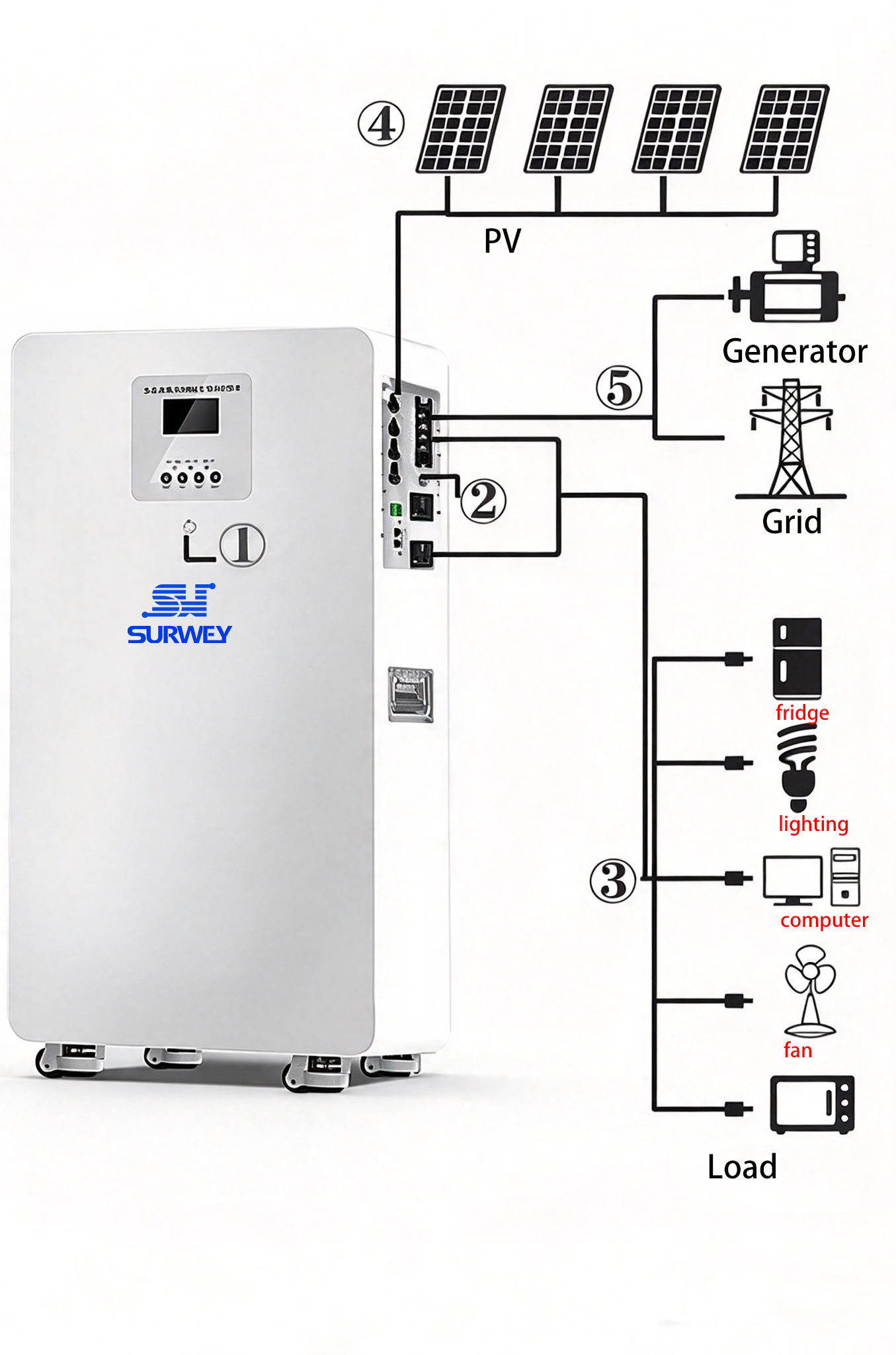
System Topology Diagram
5. Estimation of System Energy Yield
The annual peak sun hours across most of Thailand range from 4.5 h to 5 h. A midpoint value of 4.7 h is adopted for calculation. The overall system efficiency factor accounts for module temperature derating, wiring losses, soiling, MPPT tracking losses and inverter conversion losses, set at 0.8.
Formula for theoretical daily energy yield: Daily Generation = Installed PV Capacity × Peak Sun Hours × System Efficiency
Daily generation = 12.6 kW × 4.7 h × 0.8 = 47.38 kWh
Yield analysis: the system can produce approximately 47 kWh of electricity per day, far exceeding the household daily demand of 17.1 kWh. Solar power feeds loads on-site with priority; any surplus automatically charges the energy storage battery. Once the battery reaches full state of charge, excess power can be exported to the grid.
During prolonged overcast weather, peak sun hours decline sharply and generation falls. The stored battery energy then maintains essential loads. If overcast conditions persist for an extended period, the system automatically draws supplementary power from the utility grid to guarantee uninterrupted supply.
6. System Operating Modes
Video on System Operating Principles
The control unit of the all-in-one unit governs the operational logic automatically with no requirement for frequent manual switching. Four typical operating modes are defined:
- Solar Priority Mode (Sunny Daytime): PV modules generate electricity, which supplies household loads first. When PV output exceeds instantaneous load demand, surplus energy charges the battery until full.
- Battery Discharge Mode (Dusk, Night, Low Irradiance on Overcast Days): With insufficient solar generation to meet loads, the battery discharges to power the home. Discharge ceases once the battery reaches the preset cut-off threshold to prevent deep depletion.
- Grid-tied Complementary Mode: When solar and battery output combined cannot satisfy load demand, the system draws supplementary power from the grid to cover the deficit and support stable operation of high-power appliances.
- Off-grid Backup Mode (Grid Outage): Upon grid failure, the all-in-one unit rapidly switches to off-grid backup mode. Solar generation and battery storage continue to supply critical household loads, delivering uninterrupted power and avoiding disruption caused by blackouts.
7. Solution Summary
This residential PV-ESS project deploys a 12 kW / 16 kWh hybrid all-in-one unit paired with twenty 630 W N-type monocrystalline PV modules.
Note: There is an inconsistency in the original Chinese text. The string description in the final summary differs from the preceding main body. The above translation strictly follows the wording of your source document.
After electrical verification, the string Vmpp equals 209.1 V and Voc equals 246.7 V, staying steadily within the 80–450 V MPPT operating window of the all-in-one unit with ample low-temperature safety margin. The installed power remains within the equipment rating.
Calculated against local Thai solar resources, the system yields abundant daily energy to cover full household consumption. Surplus generation charges the battery for night-time supply while retaining grid-failure backup capability. The well-balanced configuration features safe and reliable electrical design, automatic control logic and low maintenance workload. It fits local household requirements as well as the regional climate and grid conditions of Thailand, proving technically feasible for field deployment.


