
Implementation Plan for a Small Hybrid PV-Storage System Addressing Household Power Pain Points in Nigeria
Across the vast lands of Africa, reliable power supply has long been a core demand for numerous households in daily life. Most parts of Nigeria are blessed with abundant solar irradiance; nevertheless, the public power grid suffers from insufficient coverage and volatile power delivery. Many local households are plagued by frequent blackouts and voltage instability over extended periods. Featuring flexible operating modes, hybrid photovoltaic‑storage systems support self‑consumption of solar power, supplementary charging from utility mains and independent off‑grid operation, making them an ideal energy solution for local families. This scheme designs a locally tailored 24 V single‑phase hybrid PV‑storage system for residential use in Nigeria.
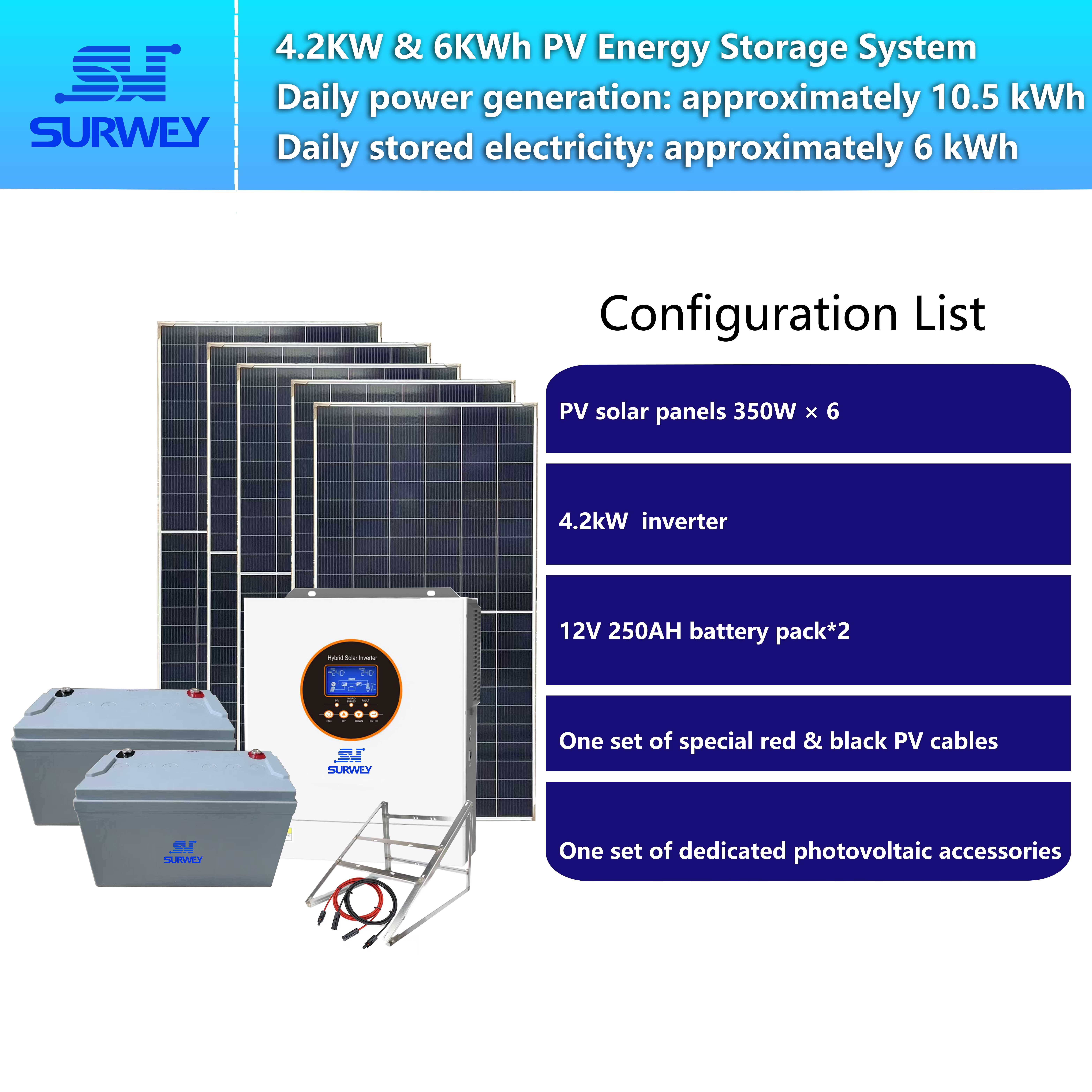
The complete system consists of one 4.2 kW‑24 V hybrid inverter, six 350 W polycrystalline PV modules and two 24 V energy storage batteries. The following text elaborates the full scheme from multiple dimensions: project background, daily power demand calculation, introduction of core components, PV string layout design, system operation logic, supporting safety design, scenario adaptability and key maintenance points.
I. Project Background, Power Consumption and Resource Conditions
Nigeria covers a wide territory with substantial differences in solar resources between the north and the south. The northern region generally achieves an average daily irradiation of 5.5–6.5 kWh/m², while the coastal south records roughly 3.5–4.5 kWh/m². Solar irradiation remains stable in the dry season, whereas cloudy and rainy days increase in the wet season. During system design, we must take into account both ample power generation in the dry season and output degradation in the wet season. The design cannot be based merely on optimal solar conditions; sufficient energy buffer shall be reserved in the storage unit to guarantee continuous supply of basic household power on overcast days.

Solar PV Panel Installation Diagram
The local power grid has distinctive features: wide voltage fluctuation range and high frequency of power cuts. Pure grid‑tied equipment can hardly operate stably under such circumstances, while standalone off‑grid systems lack utility backup for supplementary charging. Hybrid inverters perfectly adapt to this complex grid environment and enable free switching among multiple operating modes: solar‑priority power supply, supplementary charging via mains and backup discharge from batteries. The battery can be charged by mains when grid power is available, and the system automatically switches to off‑grid output once a blackout occurs. When solar generation is sufficient, solar power supplies the loads first, and surplus energy is stored in the battery bank. The whole system boasts strong fault tolerance and suits daily household use well.
This project targets an ordinary local household in Nigeria with four permanent residents. The loads are mainly basic domestic consumption with power demands both day and night. We have sorted out the on‑site verified daily power consumption list and classified loads into primary critical loads and secondary non‑critical loads to match the dual‑output management logic of the inverter.
✅ Primary Loads (highest power supply priority, connected to the main output of the inverter; power supply is retained preferentially during blackouts or low battery levels)
- Whole‑house LED lighting: 9 pieces at 12 W each, lit in segments day and night with a total daily runtime of 7 hours
- Domestic refrigerator: 1 unit rated at 110 W with intermittent compressor operation and a cumulative daily runtime of 11 hours
- TV and set‑top box: combined power of 70 W, used in the evening and night for 4 hours per day
- WiFi router and home monitoring system: combined power of 35 W, energised continuously for 24 hours
- Domestic clean‑water pump: 180 W, operated for water intake in the morning and evening with a total daily runtime of 1 hour
✅ Secondary Loads (non‑essential loads, connected to the second output of the inverter; automatically disconnected by the system when battery power is low to prioritise basic power supply)
- Standing fans: 3 units at 50 W each, used during hot periods with a total daily runtime of 7 hours
- Small washing machine: rated at 300 W, operated once a day for 1 hour
Daily Power Consumption Calculation
Primary load daily power consumption:
- Lighting: 9 × 12 W × 7 h = 756 Wh
- Refrigerator: 110 W × 11 h = 1210 Wh
- TV and set‑top box: 70 W × 4 h = 280 Wh
- Router and monitoring system: 35 W × 24 h = 840 Wh
- Water pump: 180 W × 1 h = 180 Wh
- Total daily consumption of primary loads: 3266 Wh
Secondary load daily power consumption:
- Fans: 3 × 50 W × 7 h = 1050 Wh
- Washing machine: 300 W × 1 h = 300 Wh
- Total daily consumption of secondary loads: 1350 Wh
The total daily power consumption when all household loads run simultaneously reaches 4616 Wh. In real domestic scenarios, the washing machine and fans seldom operate at the same time. Considering staggered power use, the household’s normal average daily consumption falls within 3.8–4.2 kWh, which matches the generation capacity of this PV system perfectly. Once the grid fails, the system automatically cuts secondary loads such as fans and the washing machine to keep the refrigerator, lighting, network and water pump running, ensuring the family’s basic living needs are unaffected by blackouts.

Indoor Installation Diagram of Key PV Equipment
II. Introduction to Core Hardware
2.1 4.2 kW‑24 V Single‑Phase Hybrid Inverter

4.2 kW‑24 V Single‑Phase Hybrid Inverter
The 4.2 kW‑24 V single‑phase hybrid inverter selected for this scheme serves as the core for control and power conversion of the entire system.
This inverter adopts pure sine‑wave output with a power factor up to 1.0 and low harmonic distortion. It will not generate impact on inductive loads and precision electronic equipment such as refrigerator compressors, televisions and routers. Ordinary modified sine‑wave inverters tend to cause overheating, abnormal noise or even damage when driving compressors and household appliances, risks that can be fully avoided by pure sine‑wave output. It integrates an MPPT solar charging module with an MPPT operating voltage window of 60–450 VDC and a maximum allowable open‑circuit voltage of the PV array of 500 VDC. This wide voltage range provides ample space for PV string design and adapts to multiple module series configurations. Meanwhile, the built‑in MPPT delivers high tracking efficiency, capturing the maximum power point of the PV array in real time to improve solar energy utilisation.
The unit supports practical battery‑less operation, a key advantage of hybrid inverters. Even if the battery bank fails or is temporarily removed, the system can still supply AC loads directly using solar power together with mains, instead of complete shutdown due to battery faults. This greatly improves system availability, which is highly suitable for overseas sites with long lead times for spare parts. It also features built‑in automatic activation logic for lithium batteries. After new lithium batteries are installed, the inverter can initiate the activation process independently and reduce manual commissioning work.
2.2 350 W Polycrystalline PV Modules (Power Generation Units)

Actual Photo of 350 W Solar Panel
This design adopts 350 W polycrystalline PV modules with rated parameters: Vmp = 41.15 V, Voc = 34 V and Isc = 5 A. With CE certification, they are mature and reliable products widely used in overseas residential PV projects. Polycrystalline modules perform better under low‑light conditions; their power output drops less significantly on overcast wet‑season days and in low‑light periods such as early morning and dusk compared with monocrystalline modules, matching Nigeria’s cloudy wet‑season climate.
Each module weighs 15 kg with standard dimensions and can be carried manually without heavy hoisting equipment. Featuring a stable structure and tempered glass surface with sand resistance, the modules can withstand sand erosion in northern Nigeria where sandstorms are frequent. The junction box has a high sealing protection grade, preventing rainwater and moisture from invading terminals for outdoor exposure. Six 350 W modules are deployed in the whole system for a total installed PV capacity of 2100 W. Compared with the maximum allowable PV input power of 6500 W for the 4.2 kW inverter, sufficient margin is reserved so that the MPPT rarely runs at full load for enhanced long‑term stability.
2.3 24 V Energy Storage Batteries

Two 24 V energy storage batteries are configured as the energy storage units of the system. They store solar power and act as the power source under off‑grid conditions.
The two batteries are connected in parallel on the DC side of the inverter to increase total capacity and extend the self‑sustainment duration on successive cloudy days. The inverter is equipped with dedicated battery charging curves and automatically matches charging strategies for the corresponding battery type to prevent overcharging and battery damage.
Video of System Operating Principle
III. Detailed Design of PV String Scheme: 3S2P (3 in Series, 2 in Parallel)
Six 350 W modules in total adopt a 3S2P layout: three modules connected in series form one branch, and two such branches are connected in parallel. This is the core design of the scheme.
We first calculate the electrical parameters of a single string. With Vmp = 41.15 V for each module, three modules in series produce a string operating voltage Vmp = 123.45 V. With Voc = 34 V per module, the open‑circuit voltage of one string reaches 102 V. Compared with the MPPT operating window of 60–450 VDC for the 4.2 kW inverter, the range of 102 V to 123.45 V falls safely within the normal MPPT operating band. It will neither drop below the minimum MPPT start voltage to disable generation tracking nor approach the 500 VDC open‑circuit voltage limit, leaving adequate margin for voltage fluctuation under high and low temperatures.
Inexperienced designers often make mistakes here: too many modules in series will sharply raise the open‑circuit voltage at low temperatures, which may exceed the inverter’s maximum permissible open‑circuit voltage and burn out the MPPT unit; too few modules in series will pull the operating voltage below the MPPT threshold and prevent the inverter from starting solar charging. This three‑module string keeps the voltage within a safe and stable range with considerable fault tolerance.
Current calculation: each module has a short‑circuit current of 5 A. For three modules in series, the branch current equals the module short‑circuit current of 5 A. After two branches are connected in parallel, the total PV current is 10 A. The inverter’s MPPT supports a maximum PV input current of 100 A, offering abundant current margin.
DC‑Side Supporting Safety Design
Each series branch is fitted with an independent 10 A DC fuse near the combiner terminal. In case of short circuits inside the branch or damaged cables, the fuse blows rapidly to isolate the faulty branch and protect modules, cables and the inverter. With separate fuse protection for the two branches, one branch can continue generating power while the other is isolated.
PV‑specific 4 mm² DC cables are selected for outdoor laying. They feature ultraviolet resistance and wide temperature tolerance, with controlled voltage drop to minimise resistive power losses.
The two branches feed into a combiner box and then connect to the PV terminals of the inverter. Lightning protection terminals are reserved inside the combiner box. A dedicated DC PV surge protective device is recommended for outdoor installation to mitigate induced lightning risks during Nigeria’s thunderstorm season.
Additional explanation for rejecting alternative string‑parallel layouts: a single string of six modules yields an open‑circuit voltage of 204 V. Although still within the MPPT range, the voltage is relatively high, and future capacity expansion by adding modules may easily trigger overvoltage. A 2S3P layout delivers a string open‑circuit voltage of only 68 V, close to the 60 V MPPT lower limit. Voltage may fall below the tracking threshold on cool and cloudy mornings, leading to sharp fluctuations in power generation. By comparison, the 3S2P arrangement is optimal in balancing stability, safety and operating margin.
IV. Breakdown of System Operating Modes Adapted to Nigerian Household Power Demand
The hybrid inverter supports multiple configurable operating modes. We sort out the operation logic for domestic scenarios as follows:
✅ Mode 1: Solar Priority (Recommended Default Mode for Daily Household Use) When sunlight is sufficient, the PV array generates power to supply household AC loads first. Excess power is automatically stored in the 24 V battery bank. If solar output cannot meet instantaneous load demand, stored battery power supplements the supply. Once the battery level drops to the preset threshold, the inverter activates mains power to carry loads and recharge the battery. This logic maximises solar utilisation and reduces reliance on grid electricity, suitable for long‑term use by ordinary households.
✅ Mode 2: Grid Priority When mains supply is stable, grid power feeds household loads first, while solar power and batteries serve as backups. At the moment of grid failure, the inverter switches to off‑grid supply within milliseconds. Batteries together with solar generation take over household appliances seamlessly, keeping refrigerators and routers running to avoid food spoilage and network disconnection. This mode suits households requiring uninterrupted basic power supply.
✅ Mode 3: Pure Off‑Grid Mode For residences with chronically unstable or rarely available grid supply, the system runs entirely on solar power and batteries. Solar generation charges batteries during the day, and batteries discharge to power appliances from dusk to night. Stored energy sustains loads on cloudy days. Thanks to the battery‑less operation function, even if batteries are removed under extreme conditions, solar power can directly drive loads on sunny days to guarantee basic lighting and water supply.
✅ Mode 4: Charge Priority During prolonged poor‑irradiance spells in the wet season, the system can be set to charge priority. Mains power works together with solar generation to rapidly replenish the battery bank and build energy reserves for household consumption in the following days.
Multi‑Channel Load Management Logic
The inverter provides two independent AC output channels for primary and secondary loads. During on‑site wiring, refrigerators, lighting, routers and the water pump are connected to primary load terminals; non‑essential auxiliary appliances such as fans and the washing machine are routed to the secondary output. When the battery SOC reaches the protection threshold, the inverter automatically disconnects secondary loads and maintains power for primary loads to prevent deep discharge and battery damage. For systems with limited energy storage capacity, this function effectively safeguards the baseline of household basic power supply.
V. Expected Operating Conditions and Capacity Matching Description
The total power of the PV array is 2100 W. Under favourable solar conditions in northern Nigeria with an estimated peak sunshine hour of 5.5 hours, the theoretical daily generation without considering losses is approximately 11.5 kWh. After comprehensive deduction accounting for an inverter conversion efficiency of 97 %, soiling, temperature and cable losses, the usable daily generation of the system stands at roughly 8–9 kWh. In the cloudier southern regions, the average usable daily generation drops to 5–6 kWh.
The two parallel 24 V batteries provide the required storage capacity to store surplus daytime solar power for evening and night household use. In case of consecutive cloudy days, the inverter can switch to mains charging as backup to keep refrigerators operating continuously. The inverter delivers a maximum continuous output of 4200 W and can withstand short‑term inrush loads such as refrigerator compressor startup. Nevertheless, it is recommended to limit the regular continuous household load within 3000 W to reserve operating margin for better long‑term stability.
Positioned as a residential hybrid PV‑storage power supply solution, this system features fewer components, fewer failure points and easy spare‑part management. For local Nigerian installers, the learning curve is gentle and on‑site commissioning is simple. The inverter is equipped with an LCD panel for intuitive viewing of voltage, SOC, power readings and fault codes. With optional remote WiFi monitoring, later maintenance pressure is low, and ordinary household users can also understand basic operating status.
VI. Scheme Summary and Project Value
This 4.2 kW‑24 V single‑phase hybrid energy storage scheme adopts six 350 W polycrystalline modules arranged in a 3S2P string as the PV input, paired with two 24 V energy storage batteries. Supported by the flexible multi‑mode control capability of the hybrid inverter, it precisely adapts to the residential power situation in Nigeria characterised by unstable grids and large seasonal solar fluctuations. The 3S2P string layout stabilises PV voltage within the optimal MPPT window, balancing safety, generation efficiency and long‑term reliability while avoiding common overseas PV design pitfalls such as overvoltage and undervoltage.
The hybrid architecture is the biggest highlight of this scheme. It overcomes the drawbacks of pure grid‑tied systems that fully depend on the grid and standalone off‑grid systems lacking backup, enabling intelligent coordination among mains, solar power and energy storage. Meanwhile, built‑in functions including battery‑less operation, graded dual‑load power supply, remote monitoring and compatibility with multiple battery types are practical designs targeting the pain points of African household users. Polycrystalline modules boast strong low‑light adaptability, the hardware selection is proven and the supply chain is stable. The whole system balances generation capacity, energy buffering and power supply reliability.
Against the backdrop of global energy transition, demand for distributed residential PV‑storage systems keeps rising across Africa. Such small hybrid home systems offer a stable and sustainable power pathway for ordinary households in regions with unreliable grid supply. This scheme can also serve as a standard template. Based on the same string logic, the number of modules and battery capacity can be adjusted to derive derivative schemes of different power ratings to meet the demands of more local residential projects.


