
Technical Solution for 53.6kW PV Energy Storage System of an Auto Parts Processing Plant in Czech Republic
Preface
With the continuous rise of industrial electricity costs across Europe, an increasing number of manufacturing enterprises are adopting PV + energy storage solutions to hedge against electricity price fluctuations. Tailored to the power consumption characteristics of an auto parts processing plant in Czech Republic, this solution introduces an integrated commercial and industrial system with 53.6kWp photovoltaic capacity paired with an 80kWh energy storage unit. It supports on-site self-consumption during daytime, peak shaving and valley filling during high-price periods, and emergency backup power in case of grid outages. Without disrupting production schedules, the system effectively cuts electricity expenses and improves power supply stability for the plant.
🏭 Project Overview
This project is located in Czech Republic and serves an auto parts processing plant. The factory mainly manufactures automotive metal stamping parts, welded assemblies and machined structural components, supplying nearby vehicle manufacturers and Tier 1 suppliers. It operates on a two-shift schedule with peak power demand in daytime. The plant’s electrical loads include CNC machining, stamping, welding, air compression, ventilation & dust removal, lighting and office equipment. The load profile is stable, and continuous power supply is highly critical.
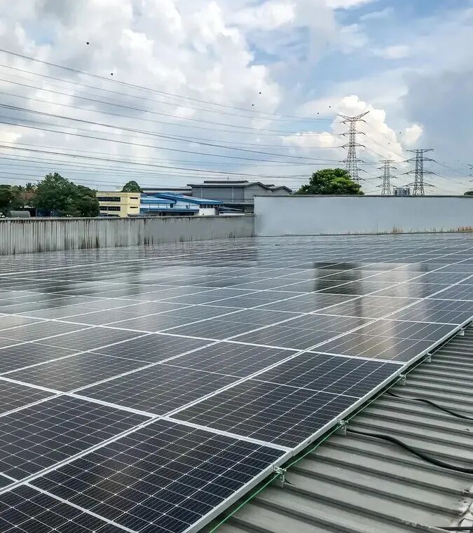
Solar Panel Array Rendering
The solution combines PV self-consumption, peak-valley regulation via energy storage and grid-tied backup operation to reduce the plant’s power cost and enhance power supply reliability.
⚙️ General System Configuration
The total installed PV capacity is 53.6kWp, equipped with a 40kW three-phase high-voltage hybrid grid-tied inverter & controller integrated machine and an 80kWh high-voltage rack-mounted energy storage battery pack. The designed average daily power generation is approximately 241kWh, and the daily energy storage capacity is around 80kWh.
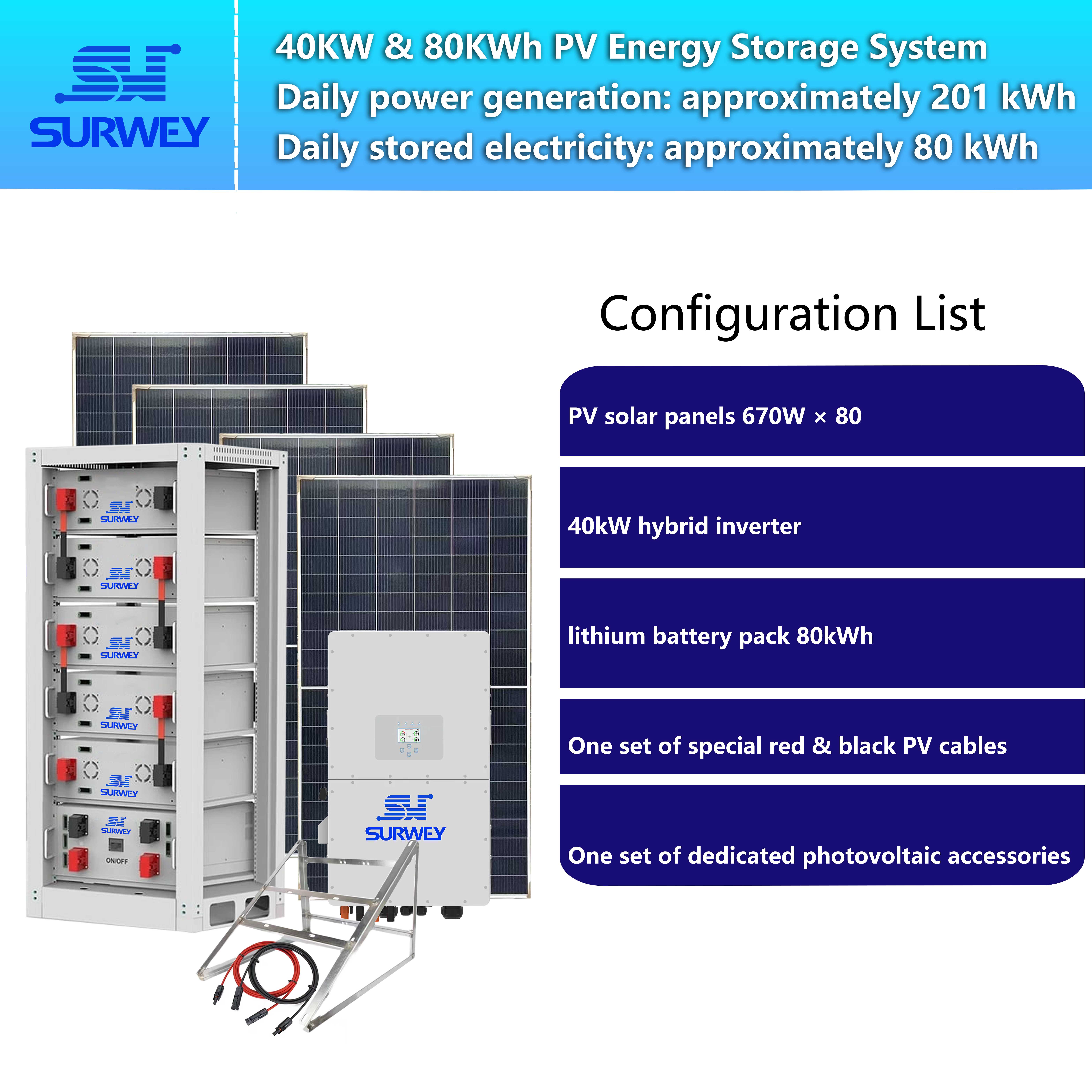
40kW / 80kWh PV-ESS Configuration Diagram
The system consists of three core components:
- PV side: 80 pieces of 670W monocrystalline silicon modules, with a total installed capacity of 53.6kWp;
- Inverter side: 1 set of 40kW three-phase high-voltage hybrid grid-tied inverter & controller integrated machine, supporting multiple operation modes: grid-tied, off-grid and backup;
- Energy storage side: 1 set of 80kWh high-voltage rack-mounted LiFePO₄ battery pack for peak shaving & valley filling and emergency backup power. The AC side of the whole system connects to the plant’s three-phase distribution network, with coordinated operation between PV and energy storage.
☀️ PV Array Design and Voltage Verification
🔹 Array Wiring Scheme
10 modules are connected in series to form one string, with a total of 8 strings. Every 2 strings are connected in parallel to one MPPT port, occupying all 4 MPPT channels of the inverter (2+2+2+2). This fully utilizes the PV access capacity and achieves optimal tracking efficiency.
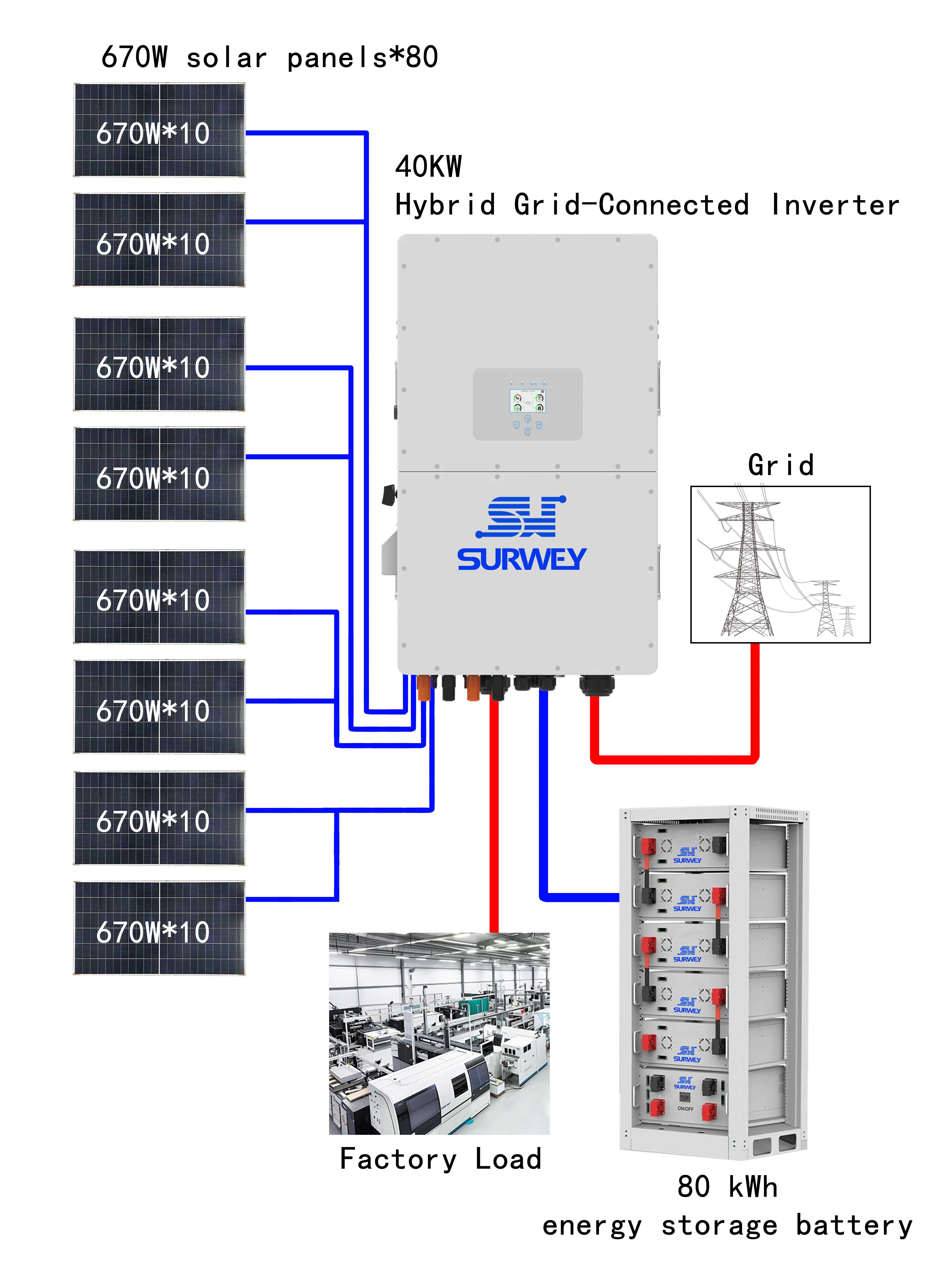
40kW / 80kWh PV-ESS Topology Diagram
Key electrical parameters of modules (STC):
- Rated maximum power Pmax = 670W
- Open-circuit voltage Voc = 46.0V
- Maximum power point voltage Vmpp = 36.1V
- Maximum power point current Impp = 13.80A
- Short-circuit current Isc = 18.42A
- Voc temperature coefficient = -0.26%/℃
🔹 Open-circuit Voltage Calculation
STC condition (25℃): Open-circuit voltage per string = 46.0V × 10 = 460V Extreme low-temperature condition check: The minimum outdoor temperature in winter in Czech Republic is assumed to be -20℃. The temperature difference ΔT relative to STC (25℃) is 45℃. The module open-circuit voltage rises at low temperatures. Corrected Voc(-20℃) = 460V × [1 + 0.26% × 45] = 460 × 1.117 ≈ 514V
Matching verification with inverter:
- Inverter MPPT voltage range: 150V – 850V
- Maximum DC input voltage of inverter: 1000V
The extreme low-temperature Voc of a single string ≈ 514V < 850V (upper MPPT limit) and < 1000V (maximum DC input voltage).
Conclusion: The open-circuit voltage of 10 series-connected modules stays steadily within the inverter MPPT operating range throughout the whole year, with sufficient safety margin, so overvoltage protection or disconnection will not occur.
🔹 Operating Point and Current Verification
Vmpp per string = 36.1V × 10 = 361V, which falls in the high-efficiency MPPT range. It rises to above approximately 400V under low winter temperatures, delivering high tracking efficiency all year round.
After 2 strings are paralleled, the operating Impp of one MPPT loop = 13.80A × 2 = 27.6A, lower than the maximum input current of 36A per MPPT channel of the inverter, indicating proper current matching.
Total DC power of 8 strings = 80 × 670W = 53.6kW. The inverter maximum DC input power is 64kW and the maximum PV access power is 80kW, leaving extra margin on the PV side.
🔋 Energy Storage System Configuration
The energy storage system for this project adopts an 80kWh high-voltage rack-mounted LiFePO₄ battery pack.
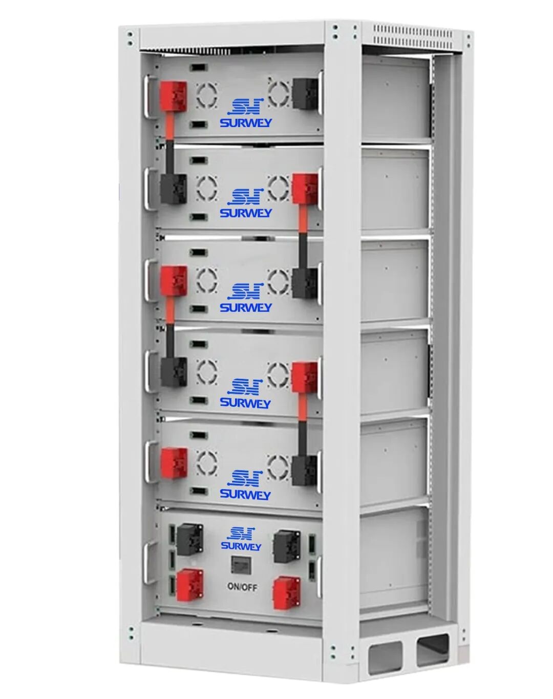
80kWh Stacked Lithium Battery Pack (16kWh × 5)
- Rated capacity: 80kWh (usable capacity approx. 73.7kWh at 90% DOD)
- Rated system voltage: 819.2V
- Operating voltage range: 672V – 928V
- Rated DC power: 80kW
- Charge/discharge current: Recommended 50A, maximum 100A
- Battery chemistry: LiFePO₄, cycle life ≥ 6000 cycles
- Communication: CAN2.0 / RS485, compatible with inverter protocols of multiple brands
The operating voltage range of this battery pack matches the high-voltage battery port of the inverter. During commissioning, the maximum charging voltage of the battery shall be limited within the allowable upper limit of the inverter. The 80kWh capacity can support peak shifting or backup power for critical plant loads for several hours.
🎛️ Inverter Selection
This project selects a 40kW three-phase high-voltage hybrid grid-tied inverter & controller integrated machine.
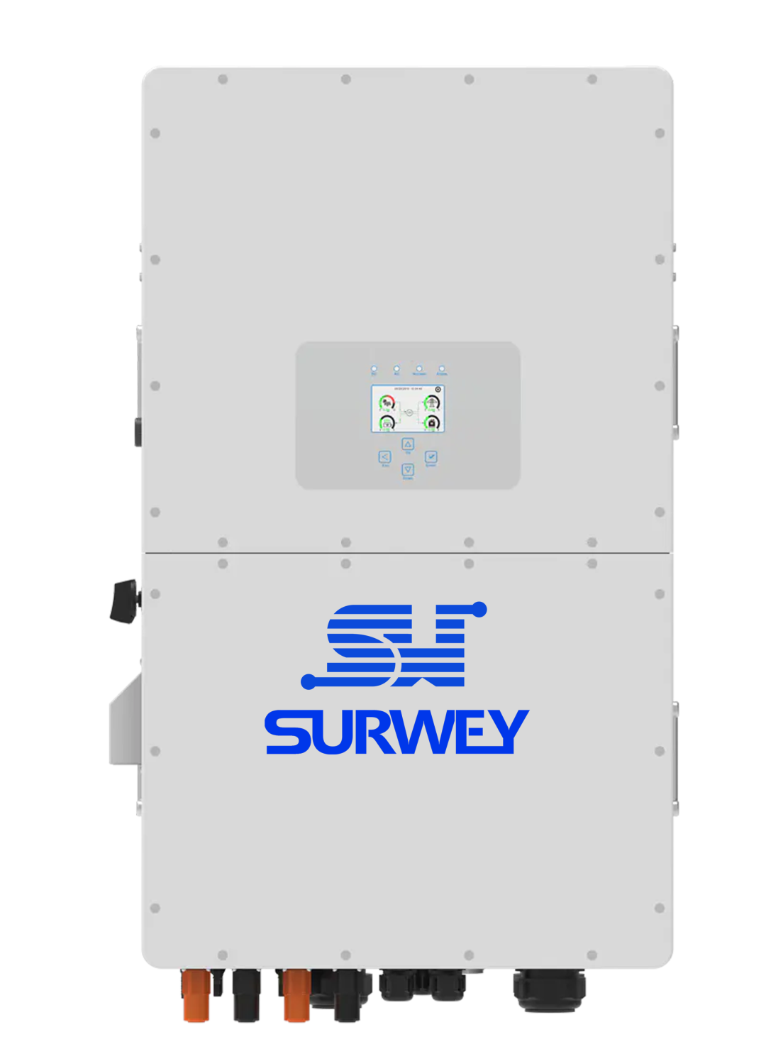
40kW Three-phase Hybrid Grid-tied Inverter
It supports three operation modes: grid-tied, off-grid and backup. Equipped with 4 MPPT channels (2 strings input per channel), maximum parallel quantity of 10 units, maximum charge/discharge current of 100A. It supports 6-period charge-discharge scheduling and diesel generator charging access. In this project, all 4 MPPT channels are connected to the PV array, and the AC side connects to the plant three-phase distribution system.
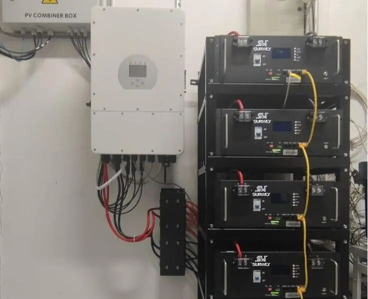
Indoor Installation View of Inverter and Energy Storage Batteries
📊 Power Generation and ESS Benefit Analysis
- Average daily power generation: Estimated based on an annual average effective sunshine duration of about 5.0h in Czech Republic: 53.6kWp × 5.0h × system efficiency (~90%) ≈ 241kWh/day
- Daily stored energy: With 80kWh rated capacity and one full charge-discharge cycle per day, the daily stored energy is approx. 80kWh.
- Self-consumption rate improvement: PV output supplies production loads with priority in daytime; surplus power charges the battery. The battery discharges during evening peak hours, lifting the PV self-consumption rate from around 60% to over 90%.
- Annual power generation: Approx. 241 × 365 ≈ 87,965kWh. Calculated against local industrial electricity tariffs in Czech Republic, the project shows favorable payback prospects.
🔌 Plant Load and Load Capacity Analysis
🔹 Main Electrical Equipment and Power
| Equipment Category | Single Unit Power | Quantity | Total Power |
|---|---|---|---|
| CNC Machining Center | 15kW | 2 | 30kW |
| Small Stamping Press | 11kW | 1 | 11kW |
| Spot Welder | 8kW | 1 | 8kW |
| Screw Air Compressor | 7.5kW | 1 | 7.5kW |
| Ventilation & Dust Removal System | 6kW | 1 set | 6kW |
| Lighting & Office Load | 5kW | — | 5kW |
| Plant Total | — | — | ~67.5kW |
The simultaneous peak load of the whole plant is around 67.5kW. PV generation can cover approximately 53.6kW in daytime, and the remaining power is supplied by the grid. Energy storage discharge during peak periods further reduces grid power draw.
🔹 Off-grid / Backup Duration
Inverter rated output: 40kW; usable ESS capacity: ~73.7kWh (90% DOD). Estimated backup duration under different load scenarios:
- Critical production load (~30kW): 1 CNC + air compressor + lighting & ventilation, backup for approx. 2.5 hours to finish in-process workpieces.
- Reduced operation load (~15kW): Lighting + office + ventilation + one small machine, backup for approx. 5 hours to maintain basic site operation.
- Minimum essential load (~8kW): Only lighting, security and ventilation, backup for approx. 9 hours to cover overnight emergency demand.
🔄 Operation Strategy
- Self-consumption Mode: PV supplies loads preferentially in daytime, surplus power charges the battery.
- Peak-Valley Arbitrage Mode: 6-period charge-discharge schedule configured. Charge during low-tariff periods and discharge during high-tariff periods.
- Backup Power Mode: Automatically switch to off-grid operation upon grid failure, prioritizing uninterrupted production for critical equipment such as CNC machines and air compressors.
- Load Management: Automatically shed non-critical loads by priority under off-grid status to extend runtime for key processes.
📖 Summary
This solution adopts 80 pieces of 670W modules (10 modules per string, 8 strings total, 2 strings per MPPT), a 40kW three-phase high-voltage hybrid grid-tied inverter & controller integrated machine and an 80kWh high-voltage energy storage battery. Rigorous voltage verification confirms that the open-circuit voltage of the PV array reaches about 514V under extreme low temperature all year round, which falls fully within the inverter MPPT range of 150–850V, ensuring safe and reliable system matching.
The system delivers an average daily generation of about 241kWh and daily energy storage of about 80kWh. Under off-grid condition, it can support critical production loads for around 2.5 hours and reduced operation loads for about 5 hours. It effectively reduces the plant’s electricity cost and improves power supply reliability.


