
6.2kW/20kWh PV-ESS Project for a Small Workshop in Tajikistan
Preface
In Central Asia, Tajikistan represents a robust market for residential and small commercial photovoltaic energy storage (PV-ESS) systems. The country’s power grid is heavily reliant on hydropower. Every winter during low-water seasons, grid capacity drops sharply, and frequent power outages and voltage dips pose severe challenges to rural workshops and small processing plants. For many local small-scale wood processors, primary agricultural product processors and handicraft workshops, blackouts directly halt production, delay order fulfillment and lead to substantial operational losses.
Compared with diesel generators, which suffer from rising fuel costs and persistent noise pollution, reliable PV-ESS systems have become the preferred power solution for many small business owners. The systems harness abundant highland solar irradiation during daytime to generate electricity. Excess power is stored in batteries to supply workshop equipment during grid outages or nighttime, delivering continuous power.
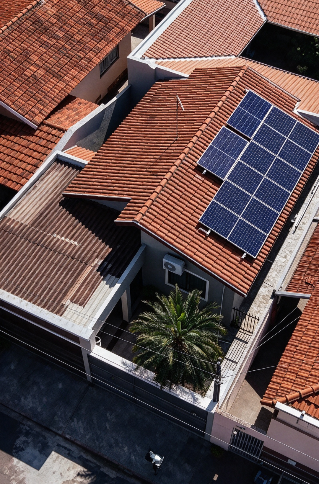
This paper takes an implemented PV-ESS project for a small workshop in Tajikistan as a case study. It conducts thorough verification and calculation of PV string voltage and current, and elaborates on design concepts, equipment selection logic under Tajikistan’s highland conditions, as well as calculations of supported load power and battery backup duration. It serves as practical reference for distributors and engineering practitioners engaged in Central Asian projects.
1. Basic Project Overview
1.1 Project Site and Power Consumption Scenario
The project is deployed at a rural handicraft workshop in Tajikistan, a typical area with unstable grid power. The local grid frequently suffers short interruptions and voltage sags, failing to sustain continuous operation of core processing equipment. Major loads at the workshop include lighting, small cutting machines, dust extraction fans and office power consumption. The design prioritizes uninterrupted power supply for fundamental production activities.
Project design targets: Daily PV generation of 23 kWh; usable energy storage capacity of 20 kWh. Solar power generated in daytime supplies workshop loads on priority. Surplus electricity charges the battery bank. During grid outages or nighttime, the storage battery discharges to power loads, enabling dual functions of self-consumption and backup power supply.
1.2 Full System Bill of Materials
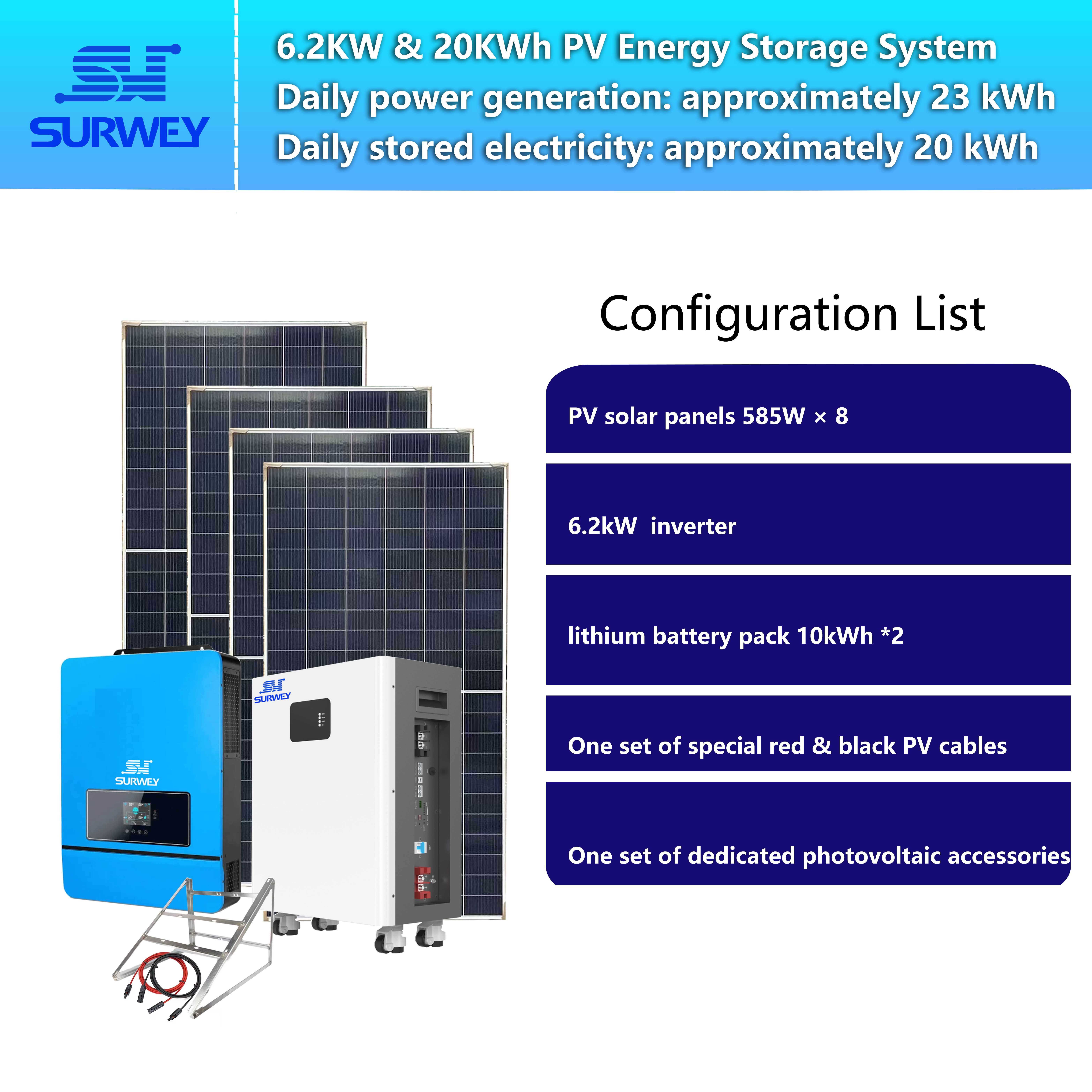
Hybrid grid-tied inverter: Pro+ series SW6.2kW, rated output power 6200 W, 48 V battery-side model, single MPPT PV channel, supports grid-tied/off-grid switching, integrated MPPT PV charge controller.
Energy storage battery: 2 units of 10 kWh floor-standing lithium iron phosphate batteries. Single unit specification: 51.2 V, 200 Ah. The two units are connected in parallel for a total capacity of 20 kWh. RS485/CAN communication supported for linkage with inverter BMS.
PV modules: 8 pieces of 585 W N-type bifacial double-glass modules. Single module power: 585 W. All modules are wired in one series string and connected to the inverter’s MPPT port.
Module parameters under Standard Test Conditions (STC): Pmax = 585 W, Vmp = 39.9 V, Voc = 47.2 V, Imp = 14.66 A, Isc = 15.58 A
Total installed PV capacity: 8 × 585 W = 4680 W. Many readers may raise a question: the inverter is rated 6.2 kW, while PV modules are only sized at 4.68 kW instead of reaching the full 6.2 kW rating. This configuration is determined by comprehensive consideration of local solar irradiance, low-temperature winter conditions and load requirements in Tajikistan.
The ambient temperature drops sharply in Tajikistan’s highland winter, causing a substantial rise in module open-circuit voltage. Too many modules in series would push open-circuit voltage beyond the inverter’s maximum MPPT withstand voltage, risking equipment damage. Meanwhile, the workshop’s daytime loads do not operate at continuous full power. Under local average irradiation, the 4.68 kW array stably yields 23 kWh daily generation, which matches the 20 kWh storage capacity without excessive wasted power, delivering superior system investment efficiency.
2. PV String Voltage and Current Verification
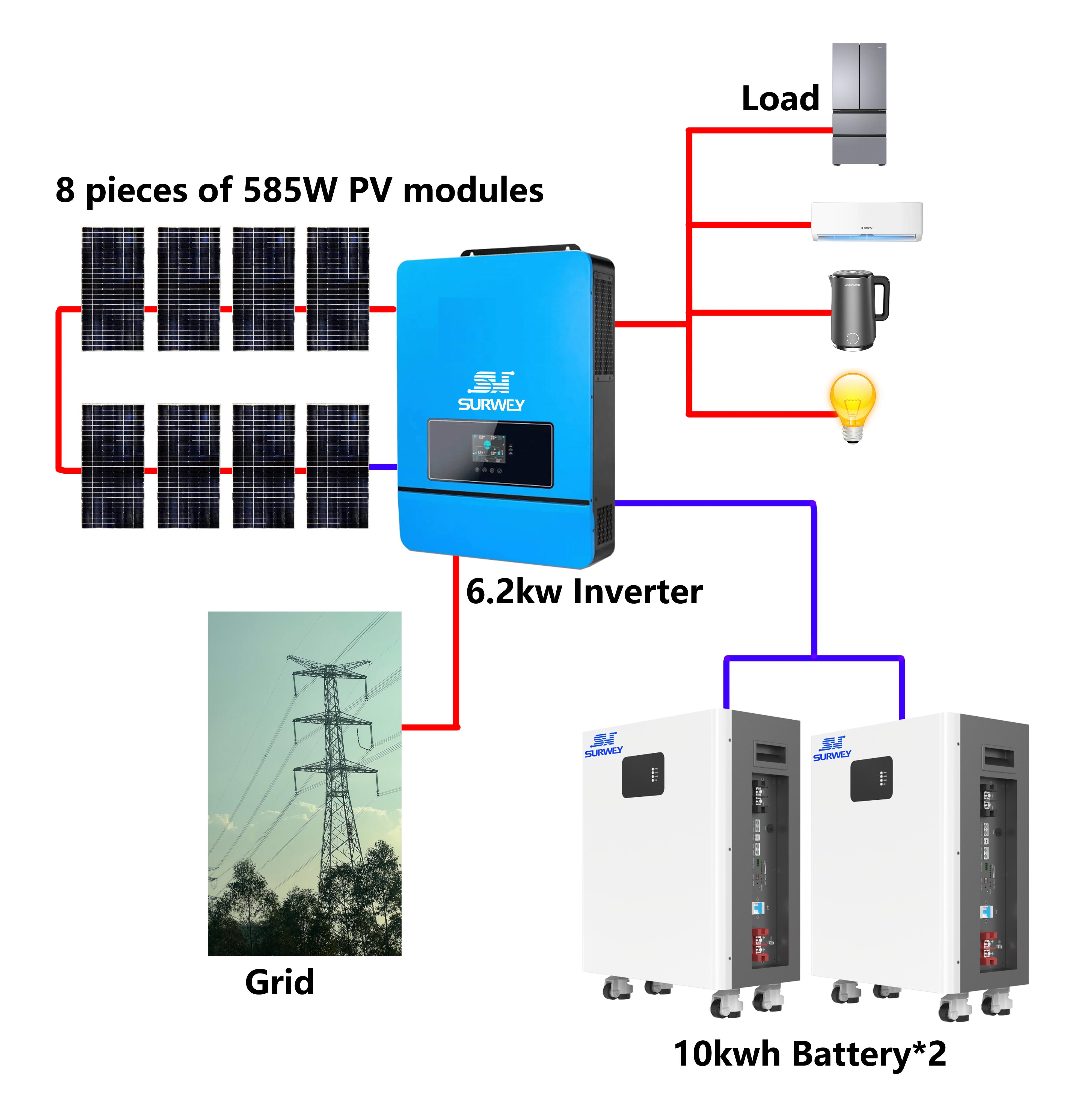
This design connects 8 pieces of 585 W modules in a single series string to feed the MPPT port of the SW6.2kW inverter. String voltage verification covers two dimensions: validation under STC ambient conditions and extreme low-temperature open-circuit voltage check. Current verification compares module operating current against the inverter’s allowable PV input current range.
2.1 String Operating Voltage Verification (STC)
Under STC, Vmp per module = 39.9 V. For 8 modules in series: Total string Vmp = 8 × 39.9 V = 319.2 V.
At first glance, 319.2 V is lower than the inverter’s minimum MPPT tracking voltage of 360 V, which may appear to indicate a flawed design. It is critical to distinguish between the 25 °C laboratory STC environment and real on-site operating temperatures.
STC is a controlled 25 °C laboratory condition. In Tajikistan, module operating temperature typically reaches 45~60 °C under sunlight. As temperature rises, module Vmp decreases; conversely, voltage rises as temperature falls. The voltage temperature coefficient of N-type modules is approximately -0.30%/°C, meaning open-circuit voltage and operating voltage rise by roughly 0.3% per 1 °C temperature drop.
During sunny mornings and cool spring/autumn periods on the highland, low module temperature elevates Vmp and brings the string voltage into the inverter’s high-efficiency MPPT tracking range. At noon, module heating reduces Vmp to around 319 V, below the 360 V MPPT lower limit. The inverter still accepts PV input and generates power, albeit with slightly reduced conversion efficiency outside the optimal MPPT window.
This represents a common engineering tradeoff for single-string designs in Central Asian highlands. The 8-module series configuration prioritizes preventing open-circuit voltage from exceeding the inverter’s 500 V DC withstand rating in frigid winter conditions to avoid breakdown risk. Slightly sub-MPPT voltage at noon is an acceptable engineering compromise.
2.2 Extreme Low-Temperature Open-Circuit Voltage Verification
STC open-circuit voltage per module Voc = 47.2 V. For 8 modules in series, STC total open-circuit voltage: 8 × 47.2 V = 377.6 V.
In mountainous Tajikistan on winter pre-dawn nights with zero solar irradiance, the minimum ambient temperature can drop to -15 °C, far below STC’s 25 °C. Lower temperature increases module open-circuit voltage. Temperature difference ΔT = 25 - (-15) = 40 °C. N-type module Voc temperature coefficient ≈ -0.30%/°C. Single-module Voc at low temperature = 47.2 × [1 + 0.30% × 40] = 47.2 × 1.12 = 52.864 V Total extreme low-temperature open-circuit voltage for 8 modules in series = 8 × 52.864 V = 422.91 V.
Maximum allowable PV input voltage of the inverter: 500 VDC.
✅ Verification Result: 422.91 V < 500 V, withstand requirement satisfied. In frigid pre-dawn winter conditions with no sunlight, the string open-circuit voltage stays under the inverter DC voltage rating, protecting the inverter from damage. This is the core safety guarantee for this series configuration.
If 9 modules were connected in series, simple calculation shows low-temperature open-circuit voltage would exceed 475 V, approaching the 500 V limit. Extreme cold snaps could push voltage past the withstand threshold and burn DC-side components of the inverter. Such risk must be avoided for highland projects in Tajikistan.
2.3 String Current Verification
Under STC, maximum power current Imp per module = 14.66 A, short-circuit current Isc = 15.58 A. For series connection, the full string operating current equals the single-module current. String Imp = 14.66 A, string Isc = 15.58 A.
Maximum PV charging current of SW6248SMHB inverter: 120 A.
✅ Verification Result: 14.66 A is far below the inverter’s maximum PV input current of 120 A, offering ample current margin. DC cables shall be sized for 16 A rating; 4.0 mm² cables fully meet ampacity requirements. Modules come with factory-fitted MC4 connectors compatible with standard PV connectors to satisfy safe current carrying.
Supplemental note: Short-circuit current Isc =15.58 A. A 20 A fuse shall be selected for single-string short-circuit protection.
2.4 Power Generation Matching Check
Total installed module capacity: 4680 W. The peak sun hours in Tajikistan are approximately 5.2 h/day. Accounting for dust shading, temperature losses, cable losses and inverter conversion efficiency with a combined derating factor of 0.8: Theoretical daily generation = 4.68 kW × 5.2 h × 0.8 ≈ 19.47 kWh. With tilted mounting and rear-side gain of bifacial modules (bifaciality 80%), ground reflected irradiance adds roughly 15% extra power output. Final daily generation can steadily reach 23 kWh, matching the project design target.
The 23 kWh daytime generation partially feeds workshop loads. Remaining power charges the 20 kWh battery bank to fully utilize storage capacity. Battery discharge depth is set at 90% to preserve battery lifespan and support production power supply at night and during grid failures.
3. Energy Storage Battery Matching Verification
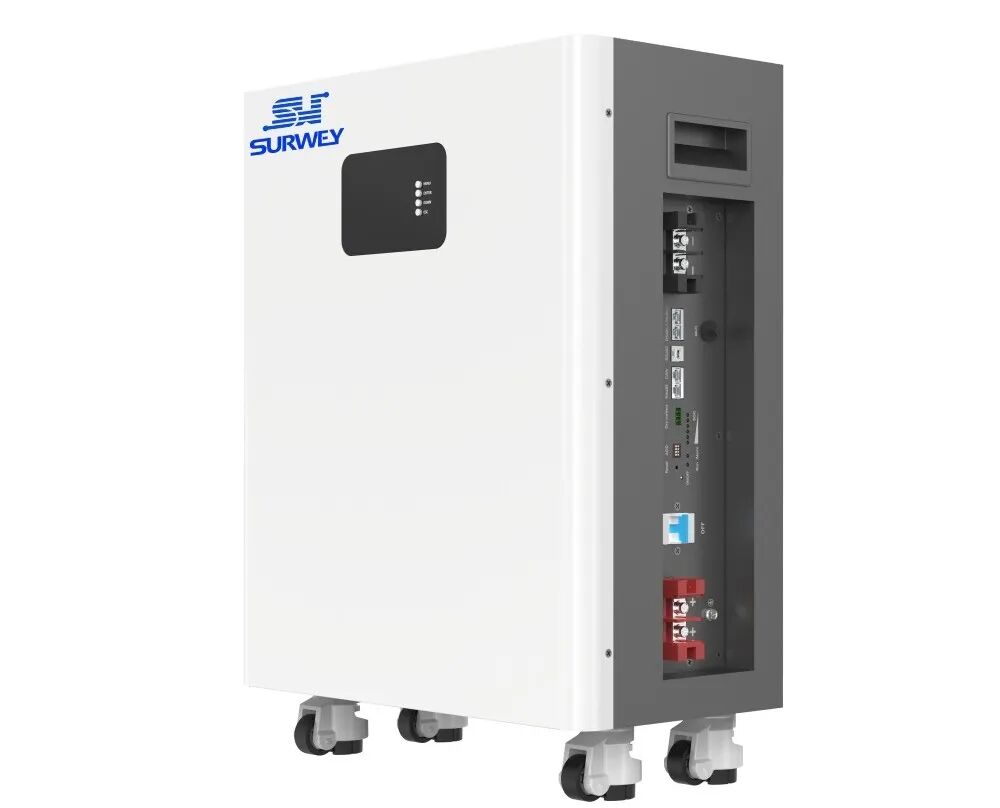
Image of a 10 kWh Floor-Standing Lithium Iron Phosphate Energy Storage Battery
Configuration: 2 units of 10 kWh floor-standing lithium iron phosphate batteries. Single unit specification: 51.2 V, 200 Ah, connected in parallel. Single battery capacity: 51.2 V × 200 Ah = 10240 Wh ≈10 kWh. Total capacity of two parallel units: 20480 Wh ≈20 kWh.
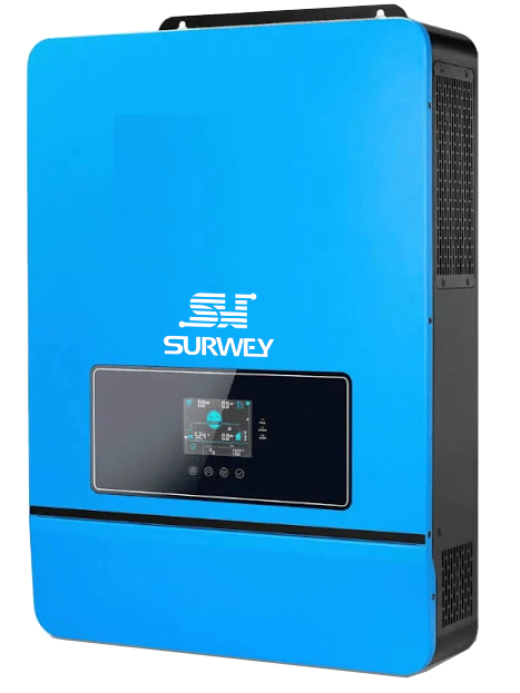
The SW6248SMHB inverter has a rated battery voltage of 48 VDC, matching the nominal 51.2 V battery. The battery BMS supports CAN communication to interface directly with the inverter. The inverter reads real-time battery voltage, state of charge (SOC), current and temperature for overcharge and over-discharge protection.
Battery operating temperature range: -20 °C ~ 55 °C. In cold Tajikistan winters, the battery incorporates low-temperature derating protection, automatically limiting charge/discharge power at low temperatures to safeguard cells, making it suitable for cold highland scenarios.
Max charge/discharge current per battery unit: 100 A. Two parallel units deliver maximum charge/discharge current of 200 A. The inverter’s maximum AC charging current is 100 A and maximum PV charging current is 120 A. Ample margin is reserved for battery charge and discharge currents.
Key battery design note: Do not place batteries directly exposed outdoors in Tajikistan’s winter. Low ambient temperature reduces usable battery capacity and shortens discharge duration.
4. System Operating Logic
This hybrid grid-tied PV-ESS system automatically switches between three operating modes.
Video Demonstrating How the System Works
Grid Normal Operation (Grid-tied Mode)
Solar power generated in daytime prioritizes workshop loads. When PV output exceeds load consumption, surplus power charges the battery bank. Once the battery reaches full state of charge, PV power is clipped. The grid acts as backup: if load demand exceeds combined PV and battery supply capacity, the grid supplements power.
Grid Outage (Off-grid Backup Mode)
The inverter automatically switches to UPS off-grid mode with transfer time ≤20 ms, so workshop equipment maintains operation without interruption. PV continues generating power to supply loads and charge batteries with excess energy. At night with no PV generation, the battery discharges to power loads until the lower SOC threshold is reached. If battery energy depletes, a diesel generator can be connected to recharge the system.
Nighttime / Heavy Overcast Conditions
No PV generation. Power is supplied by the grid when grid service is available. If grid fails, the storage battery discharges to guarantee power for core production loads.
Maximum inverter conversion efficiency reaches 98% with pure sine wave output. It does not introduce harmonic interference to small workshop motors and cutting equipment. Compared with modified sine wave inverters, it prevents motor overheating and equipment damage.
5. Supported Load Power and Backup Duration Calculation
SW6.2kW inverter rated continuous output power: 6200 W; peak power: 12400 VA. Peak power handles inrush current from motor startup. Continuous load should not exceed 6200 W for extended operation. Total storage capacity is 20 kWh. Engineering discharge depth is set at 90%, yielding usable energy of 18 kWh. All backup duration calculations are based on 18 kWh usable energy and account for inverter discharge efficiency.
5.1 Backup Duration for Different Load Levels
Light load: 1000 W (lighting, monitoring, mobile charging, small office devices) Backup duration ≈18 kWh ÷1 kW =18 hours. Sustains basic workshop lighting and security monitoring for a full night during blackouts.
Medium-small load: 2500 W (lighting + small grinders, dust extraction fans) Backup duration ≈18 kWh ÷2.5 kW =7.2 hours. Supports small-scale agricultural product grinding and simple handicraft operations for half a working day.
Medium load: 4000 W (small cutting equipment + fans + lighting) Backup duration ≈18 kWh ÷4 kW =4.5 hours. Suits the most common short-run processing scenarios for rural Tajik workshops, allowing completion of one batch of cutting work during grid outages.
Near full rated load: 6000 W (all equipment running) Backup duration ≈18 kWh ÷6 kW =3 hours.
⚠️ Note: 6 kW is close to the inverter’s 6200 W rating. Long-duration full-load operation is not recommended. Motor inrush current may trigger overload protection; this load level is only for short-time use.
Important reminder: The above values are theoretical estimates. In Tajikistan’s cold winter, usable battery capacity drops by 20%~30%, so actual winter backup duration shall be derated to 70%~80% of theoretical values. If high-power electric heating equipment runs simultaneously at night, power consumption accelerates sharply. Long-term operation of high-power electric heaters relying solely on this storage system is not recommended.
5.2 Classification of Compatible Electrical Loads
✅ Recommended loads (stable operation with pure sine wave): LED lighting, surveillance cameras, laptops, small water pumps, grinders, small cutting machines, dust extraction fans, refrigerators and other resistive/inductive small workshop equipment. The pure sine wave output ensures smooth motor operation without abnormal noise or winding burnout.
⚠️ Loads requiring caution (high inrush power): Heavy-duty wood saws, large air compressors. These motors generate high startup inrush power approaching the inverter’s 12400 VA peak rating. Start equipment sequentially instead of simultaneously to avoid inverter overload tripping.
❌ Not recommended for long-duration operation: High-power electric heaters and electric furnaces. Such devices consume power continuously at high rates and drain battery energy rapidly. Continuous high-current discharge in low winter temperatures accelerates battery degradation and shortens overall system service life.
5.3 Practical Load Operation Recommendations
- Stagger equipment startup and avoid switching all processing machines on at once to reduce instantaneous power surge.
- Arrange high-power processing tasks during daytime with available PV generation to directly utilize solar power and reduce battery consumption.
- Under off-grid backup mode, prioritize power supply for core production equipment and shut down non-essential high-power loads to extend backup duration.
- Monitor real-time load power and battery SOC on the inverter LCD display. Gradually turn off non-critical loads when SOC falls below 20%.
6. Project Summary
This 6.2kW/20kWh PV-ESS system for a small Tajik workshop uses 8 pieces of 585 W modules in one series string. Voltage and current verification confirms extreme low-temperature open-circuit voltage of 422.91 V, below the inverter’s 500 V withstand rating, with current within allowable equipment limits for safe and reliable operation.
Although string Vmp reaches 319.2 V under STC conditions, lower than the inverter’s 360 V minimum MPPT tracking voltage and operating outside the optimal MPPT window at noon, the design prioritizes DC-side safety for Tajikistan’s frigid winter climate, representing a rational engineering compromise. Leveraging rear-side gain of N-type bifacial modules, the system consistently achieves 23 kWh daily generation matching the 20 kWh storage capacity.
The system delivers rated continuous output of 6.2 kW. At 90% battery discharge depth, usable energy is 18 kWh, meeting backup power requirements for rural Tajik workshops ranging from basic lighting to medium-small processing equipment during grid failures. Lower loads yield longer backup time; high-power equipment is suitable for staggered short-time operation.
For rural workshop PV-ESS projects in Central Asia including Tajikistan, Kyrgyzstan and Uzbekistan, highland low temperature is the primary hazard. Excessive series modules leading to open-circuit voltage overshoot is the most common design pitfall. Many designers adopt module series schemes developed for lowland regions. When winter arrives, overvoltage destroys inverters. For cross-border projects, spare parts have long lead times, and equipment failure can halt workshop production for months.
PV-ESS system design is far more than simple assembly of modules, inverters and batteries. Voltage and current calculation for every string must incorporate local minimum temperature, altitude and solar irradiance. Load power and backup duration shall be estimated in advance to set clear power consumption expectations for end users. A qualified solution must fit local climate and power usage habits.


