
Technical Scheme of 50kW Grid-connected PV Energy Storage System for Industry & Commerce in Spain
📋1. Project Overview
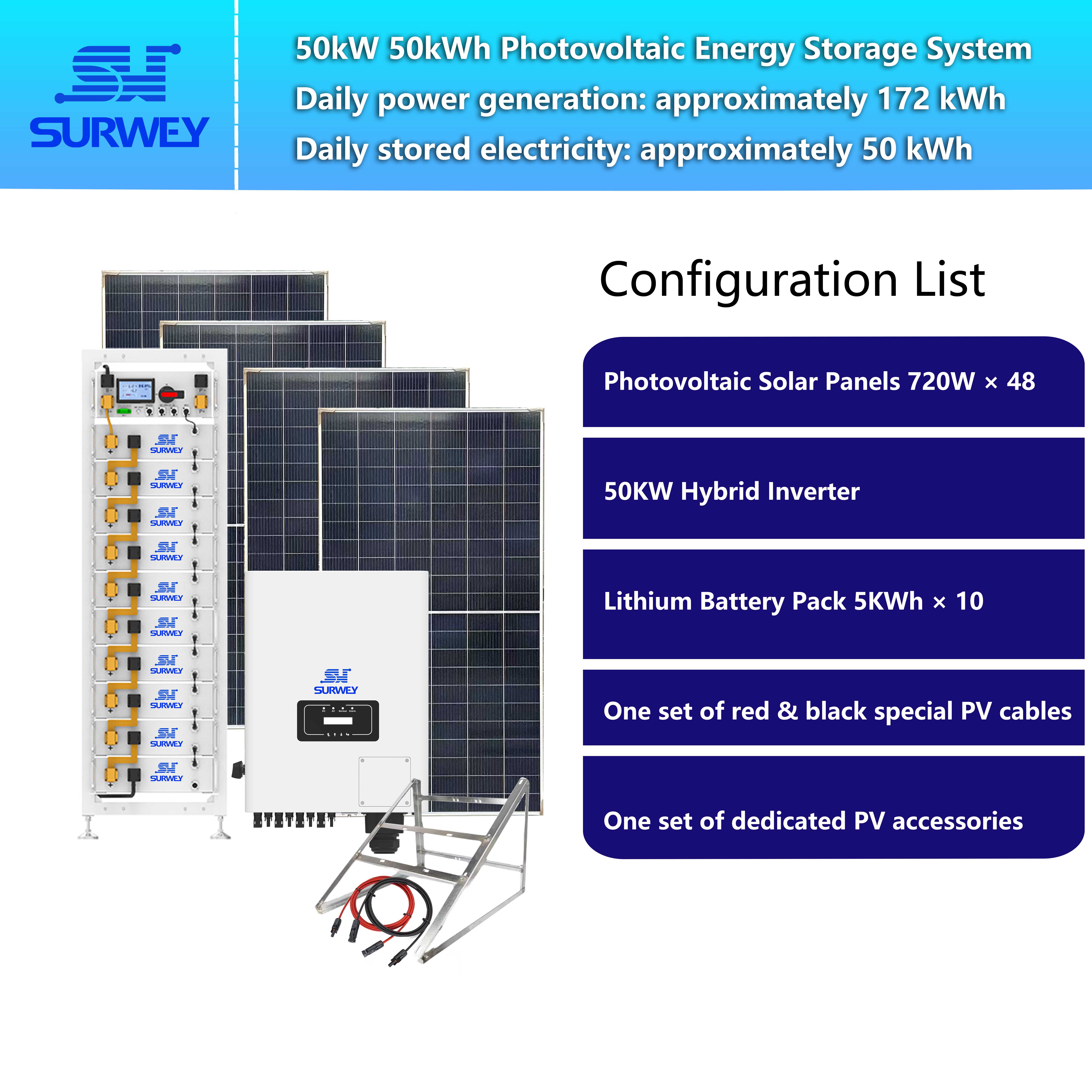
Configuration Diagram of 50kW/50kWh PV Energy Storage System
Video on Working Principle of 50kW/50kWh PV Energy Storage System
2. Basic Parameters of Core Equipment
2.1 PV Modules (720W Bifacial PV Modules)
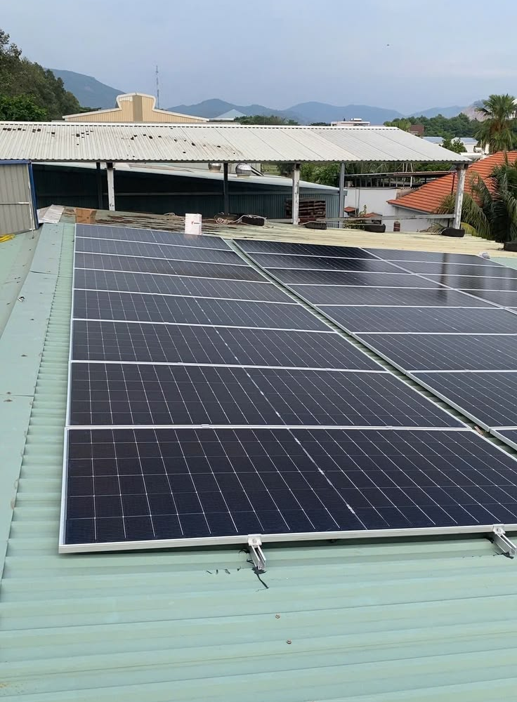
PV Array Layout Drawing on Factory Rooftop
2.2 Energy Storage Battery Modules
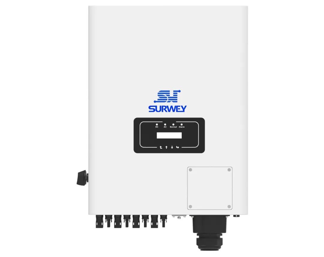
2.3 Energy Storage Inverter (50kW Three-Phase Hybrid Grid-Tied Inverter)
This three-phase 50kW hybrid inverter comes with four independent MPPT PV input channels. MPPT operating voltage range: 200V ~ 850V. DC battery access voltage range: 420V ~ 580V, compatible with the 512V high-voltage battery cluster of this scheme. It supports CAN communication to connect with the energy storage BMS.
⚡3. Series & Parallel Design and Voltage Verification of PV Array
3.1 Selection of Series Quantity per PV String
The minimum winter temperature in mountainous northern Spain reaches approximately -5°C. Low temperatures raise the open-circuit voltage of PV modules. The design requires the limit open-circuit voltage under low temperature not to exceed the inverter’s maximum MPPT voltage of 850V, and the operating voltage at normal temperature to stay above the MPPT startup voltage of 200V.
12 modules in series form one PV string: Normal-temperature open-circuit voltage per string: 12 × 50.26 = 603.12 V Low-temperature voltage calculation at -5°C, temperature difference ΔT=30°C: Low-temperature open-circuit voltage = 603.12 × [1 - 0.24% × (-30)] = 646.54 V The limit low-temperature voltage 646.54V < 850V, within the inverter’s safety upper limit. Normal-temperature operating voltage per string: 12 × 42.24 = 506.88V, falling within the inverter’s high-efficiency MPPT range of 200V~850V. The inverter can continuously and stably track the maximum PV power point.
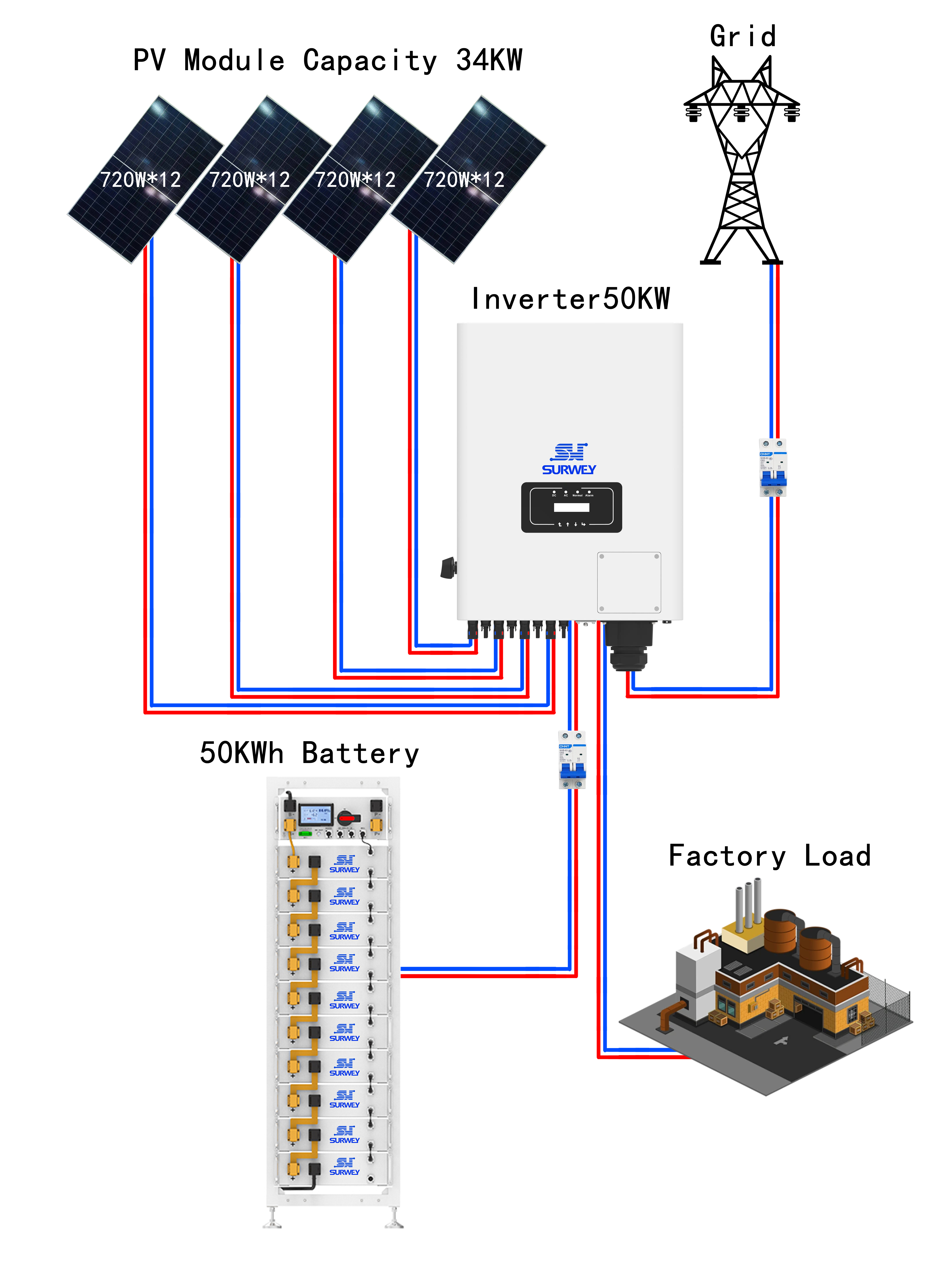
3.2 Layout of PV Strings
🔋4. Wiring Scheme of Energy Storage Batteries (10 × 5.12kWh Modules)
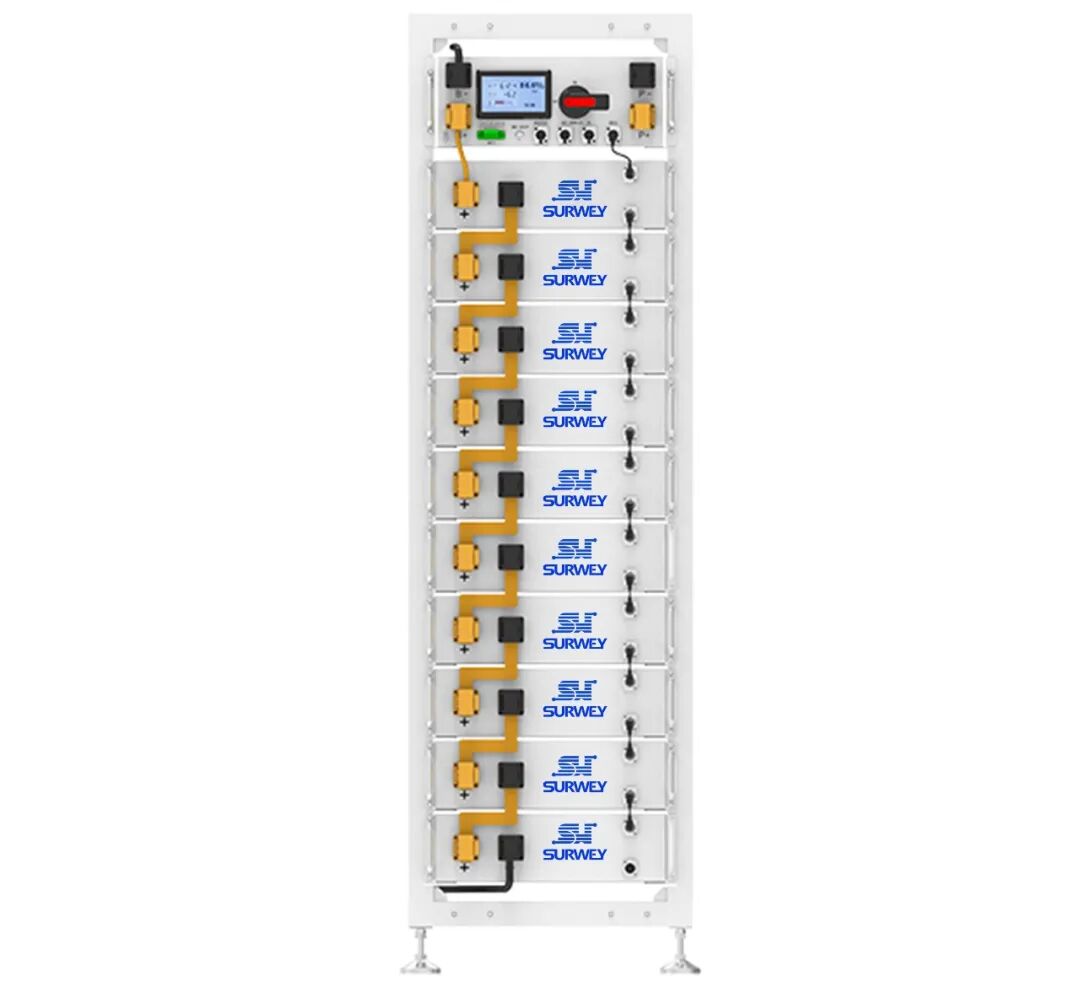
50kWh Rack-Mounted LiFePO4 Battery Pack (10 × 5.12kWh Modules)
Wiring logic: Ten battery modules are connected end-to-end in series. The overall rated voltage of the battery cluster = 10 × 51.2V = 512V, precisely fitting the inverter’s DC battery voltage window of 420~580V.
Capacity configuration: Total battery cluster capacity 51.2kWh; operating at 90% depth of discharge (DoD), available capacity equals 46.08kWh. The project is designed for daily energy storage of 50kWh. In actual operation, the upper charging SOC limit of the battery per day is controlled at 95%, delivering around 46kWh daily storage capacity. This meets storage demands while avoiding full deep charging to extend battery service life.
Communication & Installation: After series connection, modules integrate a unified BMS. The BMS interacts with the inverter via CAN2.0 bus. The inverter monitors real-time battery voltage, SOC and temperature, and intelligently manages charge and discharge logic. Batteries adopt floor-standing rack installation inside the power distribution room with ambient temperature maintained at 0~35°C. Battery cycle life ≥ 8,000 times.
📊5. Matching of Power Generation, Energy Storage Operating Conditions and Backup Load Duration
5.1 Power Generation Matching
Spain features excellent solar irradiation nationwide with an average annual effective sunshine duration of about 5.0 hours. With 34.56kW installed PV capacity, the theoretical daily power generation = 34.56 × 5 = 172.8 kWh, consistent with the project’s designed daily generation of 172 kWh.
System operation logic: PV power supplies factory loads with priority during daytime. When PV output exceeds load consumption, surplus electricity charges the battery with daily stored energy capped at 50kWh. Batteries discharge to power loads during night peak tariff hours to cut electricity costs. If surplus power remains after meeting loads via PV and storage, excess electricity is fed into the public grid.
5.2 Backup Load Equipment and Continuous Supply Duration
| Backup Load Equipment | Power per Unit | Quantity Installed | Total Load Power | Theoretical Backup Duration |
|---|---|---|---|---|
| Office Lighting | 200W | 8 sets | 1.6kW | 28.8h |
| Monitoring System | 400W | 1 set | 0.4kW | 115.2h |
| Office Computers | 350W | 4 units | 1.4kW | 33h |
| Access & Fire Control System | 500W | 1 set | 0.5kW | 92.2h |
| Mixed Simultaneous Load (All Devices Running) | — | — | 3.9kW | 11.8h |
🔄6. System Operating Modes
- PV Self-Consumption Mode: PV modules directly power factory loads in daytime and reduce mains power draw.
- Energy Storage Charging Mode: When PV output exceeds factory power demand, surplus electricity charges the high-voltage battery cluster.
- Energy Storage Discharging Mode: During night hours without sunlight and peak tariff periods, batteries discharge to supply factory loads and reduce peak electricity bills.
- Grid-Tied Mode: Excess power generated by PV and storage is exported to the public grid. When the utility grid fails, the inverter automatically switches to off-grid mode to supply emergency power for key loads.
🌟7. Scheme Summary
- PV Configuration: 48 pieces of 720W modules divided into four strings with 12 modules per string. The low-temperature open-circuit voltage is 646.54V and normal-temperature operating voltage is 506.88V, fully falling within the inverter MPPT voltage range for safe and compliant electrical operation.
- Energy Storage Configuration: Ten battery modules connected in series form a 512V high-voltage battery cluster compatible with the inverter’s DC storage voltage window. The available capacity meets the daily storage demand of nearly 50 kWh.
- Operating Condition Matching: The 34.56kW PV array generates 172 kWh daily, matching local solar generation indicators. Relying on Spain’s time-of-use tariff policy, the system realizes self-consumption and peak-valley cost reduction, alongside emergency backup power during grid outages.
- Expandability: PV strings and battery modules adopt modular structures. Additional PV strings and parallel battery modules can be added later for capacity expansion to accommodate future power consumption growth of enterprises.


