
Analysis of the Technical Solution for an 8.5 kW Residential Solar-Storage Integrated System
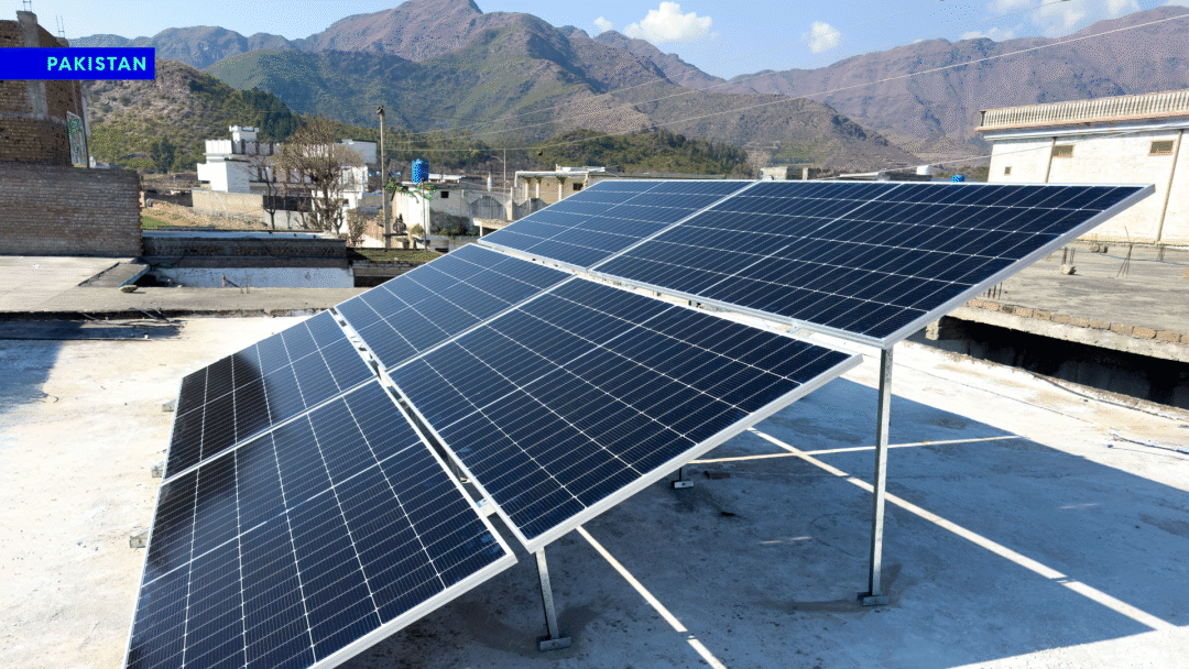
8.5 kW Residential Solar-Storage Integrated System in Pakistan
Foreword
This article provides a comprehensive overview of an 8.5 kW PV system coupled with a 16 kWh wall-mounted energy storage system. The complete system consists of a 590 W monocrystalline PV array, an 8.5 kW energy storage inverter, and an SW-T512V16KWH-S vertical lithium iron phosphate (LiFePO₄) energy storage battery, along with PV mounting brackets, DC cables, MC4 waterproof connectors, among other auxiliary materials. Based on an average of 5 hours of effective sunlight per day, the system’s average daily power generation can reach 29.5 kWh. Paired with the 16 kWh energy storage unit, it can meet diverse usage needs such as daily self-consumption, emergency power supply during outages, and peak-to-off-peak load balancing. This document provides an objective explanation across six sections: photovoltaic module configuration, inverter performance, energy storage battery parameters, system operation logic, applicable scenarios, and installation and maintenance.
Operating Principles of an 8.5 kW Residential Solar-Storage Integrated System
I. Photovoltaic Array Configuration and Electrical Matching Standards

8.5 kW Residential Solar-Storage Integrated System Wiring Diagram
In system design, the number of PV strings directly affects equipment operational safety. If too many modules are connected in series, the open-circuit voltage will rise in low-temperature environments, which can easily trigger the inverter’s overvoltage protection and cause it to shut down; if the system is divided into multiple strings, the number of cables and connectors will increase, leading to higher line losses and installation costs. This solution, featuring a design of 10 modules per string, balances electrical safety, installation costs, and roof space utilization, making it suitable for the vast majority of typical climatic conditions.
Monocrystalline modules with a 22% conversion efficiency belong to the mainstream tier of residential PV products. Leveraging mature wafer manufacturing processes, they can achieve higher power output for the same installation area. The average daily power generation of 29.5 kWh is not a theoretical ideal value; it comprehensively accounts for factors such as natural module degradation, line voltage drop, inverter energy losses, and shading caused by dust accumulation on the panels. This data closely reflects actual power generation performance in real-world use and serves as a valuable reference.
The module dimensions are suitable for flat and sloped roofs on typical residential homes and small commercial buildings. When paired with standard array mounting brackets, they meet conventional load-bearing and wind-resistance installation requirements.
The DC circuit is uniformly configured with 4-square-millimeter PV-grade cables, designed to handle the modules’ maximum operating current of 16.01 A. The standard 50-meter cable length covers the installation distance from most rooftops to the inverter; the MC4 waterproof connectors provide excellent sealing, minimizing the risk of electrical leakage or overheating failures during long-term outdoor use.

8.5 kW Residential Solar-Storage Integrated System Configuration Diagram
II. Features and Compatibility Advantages of the 8.5 kW Energy Storage Inverter
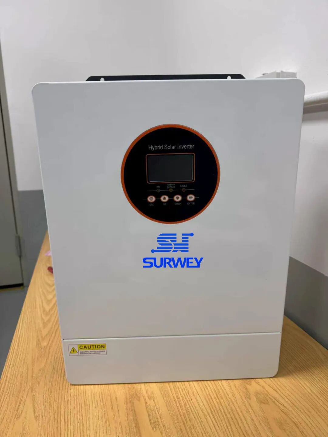
8.5 kW Low-Voltage Energy Storage Inverter
In terms of power configuration, the total PV power is 6.5 kW, while the inverter has a rated power of 8.5 kW, providing a reasonable margin of power redundancy. PV modules can only reach their rated full power during periods of strong sunlight at noon; output power drops significantly in the morning and evening, as well as during cloudy or rainy weather. This power margin helps prevent waste of peak power generation. After switching to off-grid mode following a power outage, the 8.5 kW rated output power can simultaneously power a variety of loads, including air conditioners, refrigeration equipment, lighting, and small processing equipment, meeting the combined electricity needs of both households and small businesses.
The inverter is compatible with the 51.2V energy storage battery’s communication protocol, enabling real-time monitoring of data such as remaining battery capacity, cell voltage, charge/discharge current, and equipment fault alerts. This data can be synchronized to the battery’s 3.2-inch LCD display and the accompanying smart app, providing full visibility into the system’s operational status. The unit is equipped with multiple protection features, including overvoltage, undervoltage, overcurrent, overload, high-temperature, islanding, and ground fault protection, ensuring stable operation even in grid environments with significant voltage fluctuations. Additionally, the device is compatible with over ten types of mainstream energy storage communication protocols, providing ample scalability for future expansion—such as adding batteries in parallel or upgrading the photovoltaic array—without the need to modify communication hardware.
III. SW-T512V16KWH-S Energy Storage Battery Performance Specifications
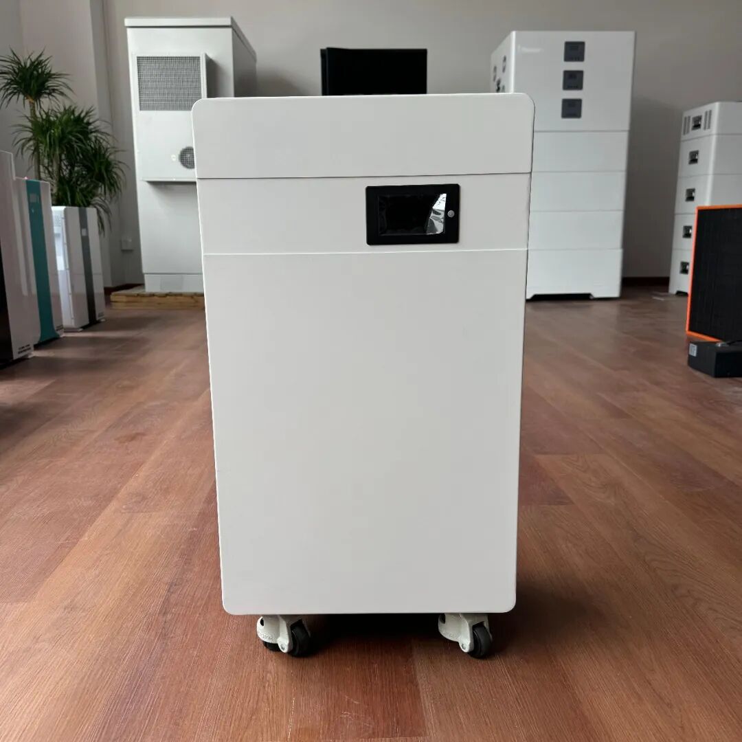
SW-T512V16KWH-S Energy Storage Battery
3.1 Battery Capacity and Battery Life Under Load
3.2 Environmental Adaptability and Service Life
The battery cells are made of lithium iron phosphate, which offers high thermal stability. They are paired with a smart BMS management system featuring built-in active balancing, which automatically corrects voltage differences between cells during operation to prevent inconsistent cell degradation. The system’s cycle life is rated under two operating conditions: ≥6,000 cycles at a constant temperature of 25°C, with 0.5C charge/discharge rates and a 90% DOD; and up to 12,000 cycles under an 80% DOD shallow discharge condition. These figures exceed the industry average for standard residential energy storage batteries, and under normal operating conditions, the system can provide stable service for over 10 years.
It features a wide operating temperature range: 0.5°C to 55°C for charging and -20°C to 55°C for discharging. It operates stably in both high- and low-temperature regions and is unlikely to trigger power-limiting protection due to excessive heat. The unit has an IP20 protection rating and supports both indoor wall-mounted and floor-standing installation options. A 3.2-inch display clearly shows battery level, charge/discharge power, and fault information. Equipped with multiple communication interfaces—including Bluetooth, RS485, and CAN 2.0—it allows users to remotely view parameters and adjust device settings via a mobile app.
IV. Overall System Operation Logic and Applicable Scenarios
Medium-to-large households: With an average daily electricity consumption of 10–15 kWh, stable daytime household electricity demand, and a high proportion of self-generated and self-consumed solar power, the energy storage can fully cover nighttime electricity consumption, reducing electricity bills over the long term;
Small retail stores and home-based workshops: These operations have relatively high daytime loads from refrigeration and processing equipment, and their commercial and industrial electricity costs are higher. Energy storage serves a dual purpose of saving electricity and providing an emergency backup power source, resulting in a shorter return on investment.
V. Installation Guidelines and Routine Maintenance Requirements
5.1 Basic Installation Standards
5.2 Routine Maintenance Tasks
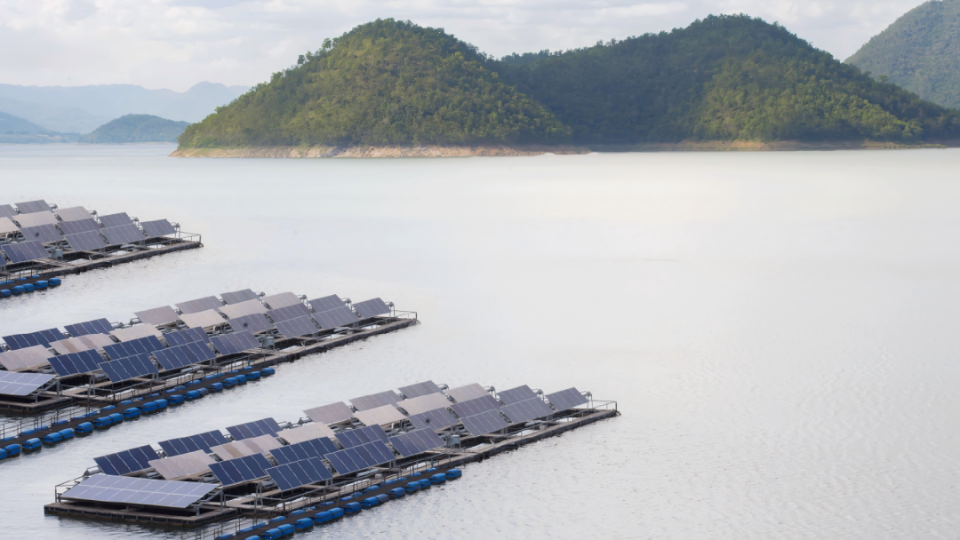
Thailand's Water-and-Solar Hybrid Floating Solar Power Plant
VI. Comprehensive Summary of the Proposal
The 8.5 kW solar-storage system consists of 10 590 W monocrystalline photovoltaic modules, an 8.5 kW energy storage inverter, and an SW-T512V16KWH-S vertical energy storage battery unit. It has been standardized and optimized across five dimensions: electrical voltage matching, power-to-capacity ratio, adaptability to diverse climatic conditions, future scalability, and O&M costs. The system’s specifications are tailored to standard sunlight conditions, residential power supply standards, and the typical electricity consumption patterns of households and small businesses. It avoids both the cost waste associated with over-specification and the risk of nighttime power shortages caused by insufficient storage capacity, while balancing power generation efficiency, runtime capacity, and equipment lifespan.
A mature and practical photovoltaic-storage system cannot be evaluated based solely on the parameters of a single component; it requires a comprehensive assessment of the synergistic performance of the photovoltaic array, inverter, and energy storage system, combined with a holistic plan that takes into account the local climate, electricity rates, and user load.


