Technical Analysis of a 240 kW Off-Grid Photovoltaic Energy Storage System
240 kW Off-Grid Solar Power and Energy Storage System Configuration Diagram
I. System Overview

Wiring Diagram for a 240 kW Off-Grid Solar Power and Energy Storage System
How a 240 kW Off-Grid Solar Energy Storage System Works
II. Technical Specifications and Selection Analysis of Core Equipment
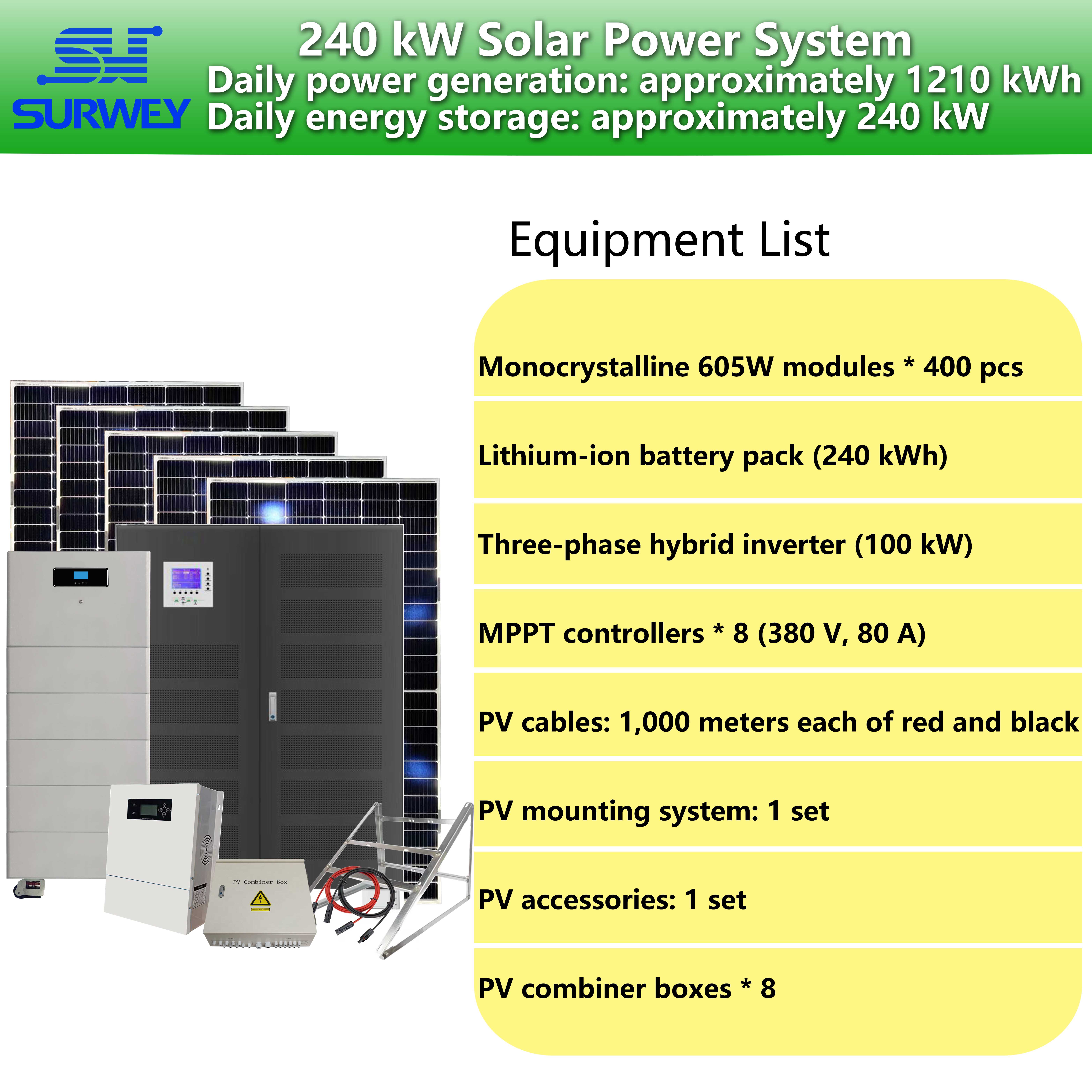
(1) Photovoltaic Modules (605W High-Efficiency Solar Panels)
The module selection and string design are closely matched to the system’s DC bus requirements: a string configuration of 10 modules in series and 5 strings in parallel is adopted. With 10 modules in series, the operating voltage of a single string is 416V (41.6V × 10), and the open-circuit voltage is 498V (49.8V × 10), which is slightly higher than the system’s 384V DC bus voltage, ensuring stable voltage output even under fluctuating light conditions; When 5 strings are connected in parallel, the operating current of a single array is 54A (10.8A × 5), and the short-circuit current is 68A (13.6A × 5). These current parameters match the 80A rated current of the downstream solar controller, providing ample current redundancy to prevent the risk of overload. The 400 modules are divided into 8 arrays (50 modules per array), with each array independently connected to a combiner box and a controller. This modular design facilitates future expansion, maintenance, and fault isolation; a failure in a single array does not affect the overall system operation, significantly enhancing the system’s fault tolerance.
(2) Combiner Box and Solar Controller
1. Junction boxes (6 inputs, 1 output; 8 units)
2. Solar controllers (SW1-80, 384 V/80 A, 8 units)
(3) High-voltage lithium-ion battery pack (240 kWh, SW-H15-240KWH)
With a capacity of 240 kWh, the battery pack effectively matches a 240 kW PV installation and a 100 kW inverter: During periods of ample sunlight, solar energy is prioritized for powering loads, with surplus energy stored in the battery; the maximum hourly charging rate can reach 80 kWh (8 controllers × 80 A × 384 V); At night or on cloudy/rainy days, the battery discharges to provide DC power to the inverter, supporting continuous discharge for a 100kW load for approximately 2.4 hours. This effectively addresses the issue of intermittent PV power supply and ensures uninterrupted operation of the load. The battery pack features a built-in BMS (Battery Management System) that monitors individual cell voltage, temperature, and SOC (State of Charge) in real time. It includes protection against overcharging, over-discharging, overcurrent, high temperature, and low temperature. In the event of an anomaly, the system rapidly disconnects the circuit and triggers an alarm. Additionally, it supports expansion with battery inspection modules, enabling precise localization of faulty cells for rapid maintenance and reduced O&M costs.
(4) Off-grid inverter (SW-TP-100, 100 kW)
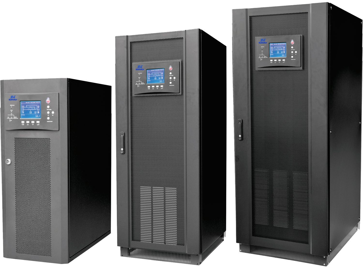
100kW Three-Phase High-Power Off-Grid Inverter
High-Efficiency and Stable Output
Inverter conversion efficiency >85%, Sixth-generation IGBT power devices feature high-speed switching, low saturation voltage drop, low losses, and low temperature rise, ensuring efficient operation under high-power conditions and minimizing energy loss; the inverter produces a pure sine wave with total harmonic distortion (THD) of the phase voltage <3% (at 100% linear load). The clean waveform is suitable for various loads, including precision instruments and industrial motors, preventing equipment damage caused by harmonic distortion.
Strong Load Adaptability
Supports 0%–100% load step changes, capable of handling complex operating conditions such as load start/stop and power fluctuations; Capable of withstanding 130% overload for 10 minutes and 130%-150% overload for 60 seconds, handling short-term surge loads; supports continuous operation with 100% load imbalance, accommodating three-phase load imbalance scenarios with stable output voltage, static error ≤±1%, and dynamic error ≤±3%, delivering power quality that meets utility grid standards.
Comprehensive Protection Mechanisms
Integrated with multiple intelligent protections, including input/output overvoltage and undervoltage, surge, phase sequence, overload, short circuit, high temperature, and battery overcharge/overdischarge. In the event of a fault, it triggers real-time alarms and cuts off the output, ensuring comprehensive system safety; Equipped with RS232/RS485 communication interfaces, supporting remote monitoring and control, allowing real-time viewing of system operating parameters and fault information, facilitating remote operation and maintenance.
Industrial-Grade Reliability
Features a three-phase, four-wire design with wide-range AC output compatibility (220V/380V/400V/415V) to meet load requirements in various regions; offers strong environmental adaptability with an operating temperature range of 0–40°C and relative humidity ≤90%, ensuring long-term stable operation in outdoor industrial environments; features a compact overall structure with dimensions optimized for high-power heat dissipation, and a moderate weight for easy installation and maintenance.
III. Overall System Architecture and Operating Principles
(1) System Architecture Design
The PV collection unit consists of 400 605W PV modules, divided into 8 arrays, each comprising 50 modules (10 strings in series and 5 in parallel). The combiner control unit includes 8 6-input/1-output combiner boxes and 8 SW1-80 solar controllers; each PV array corresponds to one set of combiner and control equipment, enabling power consolidation, maximum power point tracking, and charge management. The energy storage unit consists of one 384V/240kWh high-voltage lithium-ion battery pack, connected in parallel to the DC busbar to serve as an energy buffer and backup power source; the inverter output unit comprises one SW-TP-100 inverter, connected to the DC busbar, which converts DC power into three-phase 380V/50Hz AC power to directly supply industrial loads.

Ocean Electric Company 200 kW Solar Power Plant Installation Project
(2) How the System Works
The system operates under four main conditions: solar power generation, battery charging, battery discharge, and fault protection, ensuring a stable power supply at all times:
Adequate sunlight conditions
Photovoltaic modules absorb light energy and convert solar energy into direct current (DC). After being collected in the combiner box, the solar controller performs Maximum Power Point Tracking (MPPT) and outputs a stable 384V DC voltage to the DC bus. At this time, the PV output power is prioritized for the inverter, which converts it into alternating current (AC) for use by the load; if the PV output power exceeds the load power, the excess energy is automatically stored in the lithium-ion battery bank via the controller until the battery is fully charged.
Low Light / Nighttime Conditions
When the PV modules produce insufficient power or no output, the lithium battery bank automatically discharges to provide 384V DC to the DC busbar, allowing the inverter to operate normally and continue supplying power to the loads. When the battery SOC drops to the preset lower limit, the system triggers low-battery protection, prioritizing power supply to critical loads to prevent battery damage from over-discharge.
Load Fluctuation Conditions
The inverter features strong load adaptability, responding in real time to changes in load power. The PV and energy storage systems work in coordination to rapidly adjust output power, ensuring stable voltage and frequency and preventing system shutdowns caused by load fluctuations.
Fault Protection Scenarios
All system devices are equipped with multiple layers of protection. In the event of abnormalities such as overvoltage, overcurrent, short circuits, overheating, or battery faults, the corresponding device rapidly disconnects the faulty circuit. The inverter issues a real-time alarm and displays a fault code, enabling O&M personnel to quickly locate the fault, ensure system safety, and prevent the fault from escalating.
IV. Technical Advantages and Innovations
(1) Highly adaptable string design for maximum light utilization
(2) Synergy between Solar Power and Energy Storage: Addressing the Challenges of Intermittent Power Supply
(3) High-power pure sine wave inverter with industrial-grade power quality
(4) Multiple layers of intelligent protection ensure system security and reliability
(5) Industrial-grade environmental adaptability, suitable for complex operating conditions
V. Application Scenarios and Value Analysis
(1) Application Scenarios

Ocean Electric Company 200 kW Solar Power Plant Installation Project
(2) Value Analysis
Economic Value
By replacing traditional diesel generators, it eliminates the need for diesel fuel, significantly reducing operating costs. With a service life of ≥25 years for photovoltaic modules, ≥10 years for battery packs, and ≥15 years for inverters, the system offers low lifecycle maintenance costs and a high long-term return on investment.
Environmental Value
Utilizing clean solar energy, it produces zero carbon emissions and zero pollution, aligning with the principles of green and low-carbon development. It contributes to achieving carbon neutrality goals and reduces reliance on traditional fossil fuels.
Safety Value
Multiple intelligent protection mechanisms and end-to-end security safeguards enable rapid fault isolation, preventing equipment damage and safety incidents; off-grid independent operation ensures strong power supply stability, unaffected by grid fluctuations or power outages.
Flexibility Value
Modular design and flexible scalability accommodate varying power load requirements; remote monitoring and maintenance reduce labor costs, improve management efficiency, and meet operational needs in remote locations.
VI. Conclusion


