
Even deep in the wilderness, it keeps watch 24/7 — a 2 kW off-grid solar power system supporting a project with multiple monitoring points.
For many field security applications where municipal power grids are unavailable, delivering consistent power to video surveillance cameras in mountainous and remote locations has long been a major headache during project deployment. Long-distance cabling carries high costs and poses construction difficulties. Trenching and erecting transmission lines take a long time and are constrained by terrain, weather and environmental protection rules. Against this backdrop, off-grid solar photovoltaic power supply solutions have become an ideal option for field security surveillance projects. This project serves multiple scattered remote surveillance nodes using a 2 kW-class off-grid PV and energy storage system to supply independent round-the-clock power for all security equipment. This article reviews the full implementation workflow from the client’s actual requirements, hardware selection, electrical parameter verification, equipment configuration at each node, system operation logic, operational precautions to later maintenance guidelines.
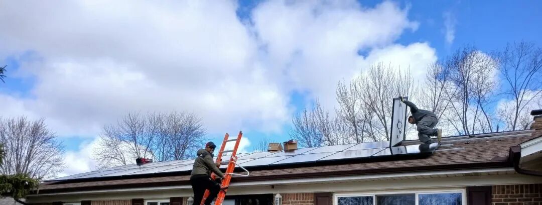
PV Module Installation Drawing
I. Client Requirements
The project site lies in a power-isolated wilderness area with several independent surveillance nodes plus a core server room. None of these locations have access to the public grid, so an off-grid solar storage system must deliver uninterrupted power to sustain the full suite of security hardware for video capture, data transmission, storage and display.
The security load includes numerous fixed and PTZ cameras, multiple PoE switches, network video recorders, display terminals, routers and wireless bridges, with reserved interfaces for power expansion of a compact communication base station. The hardware is deployed across eight nodes with distinct configurations as listed below:
- Node 1: 6 fixed cameras, 1 × 8-port PoE switch
- Node 2: 6 fixed cameras, 1 × 8-port PoE switch
- Node 3 (Core Server Room): 7 fixed cameras, 1 × 24-port PoE switch, 1 router, 1 × 64-channel 16-bay NVR, 1 × 55-inch monitor; extended backup runtime is required for this node
- Node 4: 1 PTZ camera, 8 fixed cameras, 1 × 16-port PoE switch
- Node 5: 8 fixed cameras, 1 × 16-port PoE switch, 1 × 64-channel 16-bay NVR, 1 × 22-inch display
- Node 6: 6 fixed cameras, 1 × 8-port PoE switch
- Node 7: 3 fixed cameras, 1 × 8-port PoE switch, 1 wireless bridge
- Node 8: 3 PTZ cameras, 1 × 8-port PoE switch, 4 wireless bridges
Continuous video recording must run at all surveillance points. Even during prolonged overcast spells with insufficient solar irradiance, the battery bank shall keep the hardware running without power loss or recording interruption. This fully off-grid setup relies entirely on solar harvesting and stored energy; the inverter provides properly matched operating voltage to maintain stable operation of the whole security ecosystem.
II. Hardware Selection for the Off-Grid PV System
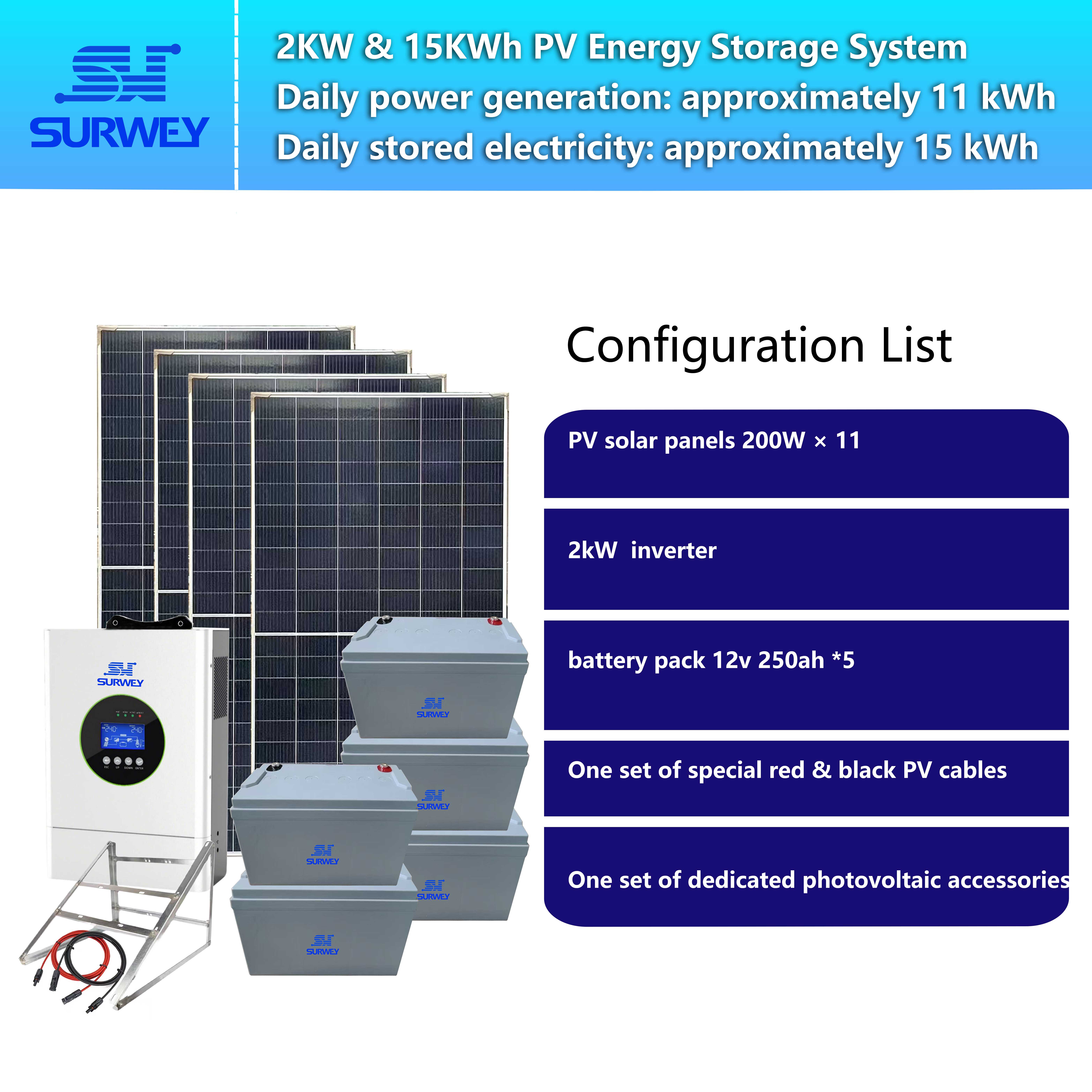
Tailored to the grid-free wilderness environment and multi-load security setup, this off-grid PV energy storage system consists of five core assemblies: solar PV modules, integrated MPPT off-grid inverter-charger, valve-regulated lead-acid battery bank, mounting brackets, plus cables, auxiliary parts and basic service tools.
2.1 Solar PV Modules
Monocrystalline solar panels are adopted. Each module is rated at 200 W with the following electrical ratings: open-circuit voltage 22.01 V, short-circuit current 11.21 A, maximum power voltage 18.72 V, maximum power current 10.68 A. Eleven panels are deployed in total.
To fit the MPPT voltage window of the inverter-charger, all eleven panels are connected in a single series string. Calculated array parameters: maximum power voltage of the string = 11 × 17.02 V = 187.22 V; open-circuit voltage = 11 × 20.43 V = 224.73 V; string operating current = 12.63 A.
The integrated unit accepts an MPPT input range of 30–400 V DC. The stacked string voltage falls well within this operating window, and the 12.63 A string current is below the maximum allowable MPPT input current of 14 A. This configuration is electrically safe with no risk of overvoltage or overcurrent damage.
These panels feature proven outdoor weather resistance to cope with drastic diurnal temperature swings, wind, rain and sunlight. Dedicated mounting racks secure the array at an optimal tilt and azimuth to maximize solar capture.
2.2 Integrated Off-Grid Inverter-Charger

One 2 kW off-grid inverter-charger is installed. This all-in-one unit integrates an MPPT charge controller and inverter, removing the need for a separate charge controller. Key specifications: rated output power 2 kW, maximum supported PV array power 3000 W; MPPT operating range 30–400 V DC; maximum PV charging current 100 A; maximum AC charging current 100 A; output: 220–240 V, 50 Hz AC.
The unit converts direct current from the PV array, tracks the maximum power point to charge the battery bank efficiently, and inverts DC power from batteries into standard AC power for switches, recorders, monitors and other security loads. Built-in protection covers overvoltage, undervoltage, overcurrent, overtemperature and short-circuit faults to mitigate electrical hazards in remote locations.
2.3 Lead-Acid Energy Storage Battery Bank

12 V 250 Ah Energy Storage Lead‑Acid Battery Bank
Five 12 V, 250 Ah valve-regulated sealed lead-acid batteries form the energy reservoir. In sunny hours, excess solar power is stored in the bank. At night or during poor irradiance on cloudy days, the batteries discharge to sustain the surveillance hardware.
Given the requirement for extended backup runtime at the core server room, the battery capacity is dimensioned primarily to keep the NVRs, hard drives and display equipment online. These maintenance-free sealed batteries suit installation in outdoor cabinets and enclosures, requiring no regular electrolyte top-up and fitting sites with limited access for servicing. Heavy-gauge DC cabling between batteries and the inverter-charger is selected to minimize voltage drop and line losses.
2.4 Brackets, Cables and Auxiliary Materials
Heavy-duty outdoor mounting brackets with anti-corrosion coating secure the PV array against strong winds. The package includes DC PV cables, AC output cables, terminals, insulation fittings and basic troubleshooting tools. All outdoor joints are fully waterproofed to reduce leakage and oxidation failures.
III. System Operating Logic
Video of System Working Principle
This standalone off-grid system operates in two primary phases: charging in daylight and discharging after dark.
When sunlight is adequate, the PV array generates DC power fed into the integrated unit. Its MPPT controller continuously tracks the maximum power point. Solar energy first supplies the live security loads; if real-time generation exceeds instantaneous consumption, surplus power charges the battery bank.
After sunset or when weak sunlight limits PV output, the system automatically switches to battery discharge mode. DC power drawn from the battery bank is inverted into 220 V AC to keep cameras, PoE switches, NVRs, displays and bridges operational.
Onboard battery management continuously monitors terminal voltage. When the state of charge hits the undervoltage threshold, protective shutdown prioritizes critical loads such as storage hardware in the core server room to prevent permanent degradation from deep discharge. Charging resumes automatically once solar irradiance recovers.
It should be noted that this is a grid-independent system with no mains backup; battery capacity dictates survivability through cloudy periods. During commissioning, the expected load draw must be cross-checked against local average consecutive cloudy days for the core server node. Load profiles differ between nodes; PTZ cameras draw transient peak current while panning and tilting. Commissioning records capture peak power consumption at each location to avoid exceeding the inverter’s output rating.
IV. Overview of Security Hardware by Node
Eight geographically separated nodes carry different camera counts and matching switching, storage and transmission hardware. Fixed cameras capture static views; PTZ units enable wide-area scanning with pan, tilt and zoom. PoE switches deliver both power and data over a single Ethernet cable, simplifying field wiring. Network video recorders handle footage archiving; both the core server room and Node 5 use 64-channel 16-bay NVRs to accommodate high-capacity continuous recording. Local displays offer live preview, wireless bridges bridge long distances where cabling is impractical, and the router manages network routing across the surveillance cluster.
Node 3 functions as the central data hub with seven fixed cameras, a 24-port PoE switch, router, high-capacity NVR and a 55-inch display. Its power profile is prioritized during configuration for longer backup runtime. A ninth node is reserved for a compact base station; available power headroom is retained, and load verification will follow once the base station power demand is finalized.
V. Verification of PV String Matching
The PV array uses a single series string of 11 modules:
- Array maximum power voltage: Vmp_array = 11 × 17.02 V = 187.22 V
- Array open-circuit voltage: Voc_array = 11 × 20.43 V = 224.73 V
The string voltage lies safely within the inverter’s 30–400 V DC MPPT tracking window, enabling stable maximum power point tracking while avoiding loss of lock at low voltage or breakdown of power semiconductors from overvoltage. The series current equals the module maximum power current of 12.63 A, below the 14 A MPPT channel limit with comfortable margin against DC overcurrent protection. Combined checks on open-circuit voltage, operating voltage and string current confirm good impedance matching between the PV array and inverter-charger. The hardware stack meets electrical ratings for reliable energy conversion and battery charging.
VI. Environmental Limits and Risk Warnings
The performance of this off-grid PV system is directly tied to local solar resource. Seasonal variation exists: shorter daylight and weaker irradiance in winter reduce generation compared with summer. Output drops sharply during extended cloud cover or fog, forcing the system to rely on stored battery energy.
Project planning must reference meteorological and irradiation datasets for the site to validate whether battery capacity can survive the longest expected cloudy sequence. If the local overcast cycle is prolonged, battery expansion may be considered later based on operational logs to satisfy the core server room’s extended runtime requirement.
Lead-acid batteries are consumables whose capacity gradually declines with charge-discharge cycles. Deep discharge should be avoided in routine operation, and undervoltage protection parameters must not be altered arbitrarily, as repeated deep cycling drastically shortens service life.
Lightning poses a major hazard in wilderness areas. Surge protection devices are fitted on both the DC PV side and the AC output side, and all enclosures are reliably earthed to reduce the risk of equipment damage from induced lightning transients.
VII. Project Conclusion
For remote security deployments without grid access, off-grid PV energy storage eliminates the prohibitive expense of long-distance power line construction. This implementation uses eleven 200 W panels in series, paired with a 2 kW integrated off-grid inverter-charger and five 12 V, 250 Ah lead-acid batteries. Rigorous electrical validation confirms the string voltage and current fit the unit’s operating envelope. The configuration delivers autonomous uninterrupted power for fixed cameras, PTZ cameras, PoE switches, NVRs, monitors and wireless bridges, while reserving capacity for a future communication base station.
Nevertheless, an off-grid PV installation is not maintenance-free. Actual performance depends heavily on solar availability, battery health, load peaks and construction quality. Stable year-round surveillance hinges on careful design, proper wiring and scheduled inspections. Field conditions expose hardware to temperature extremes, dust, wind, rain and lightning. Strict adherence to electrical design and consistent preventive maintenance unlock the full potential of off-grid solar and keep remote security cameras online 24 hours a day.


