
Sunshine Against Power Outages: In-depth Analysis of a 500kW Hybrid Grid PV-ESS Project in Côte d’Ivoire
Introduction
West Africa boasts excellent solar irradiance. However, grid fluctuations, intense heat and solar exposure, and large diurnal temperature differences create hidden pitfalls for projects. Many assume that simply mounting PV modules and energy storage cabinets on rooftops delivers a fully functional system. In reality, module string configuration, equipment coordination, and the power flow across the whole system day and night determine actual project performance. Drawing on this real 500kWp commercial and industrial PV-ESS project in Côte d’Ivoire, we discuss hardware features, PV string design, and the complete operating logic of the system.
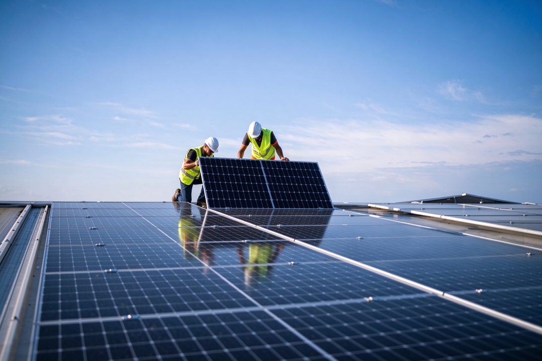 PV Module Installation Diagram
 PV Module Installation Diagram
Located in West Africa, Côte d’Ivoire sees robust growth in commercial and industrial sectors with abundant solar resources. Factories generally own large rooftop areas, making them ideal for PV and energy storage deployment. Nevertheless, the local power grid infrastructure is relatively underdeveloped. Unexpected outages and voltage fluctuations are common. Most factories rely on diesel generators for emergency backup, incurring continuous costs for fuel consumption and equipment maintenance.
The project has an installed PV capacity of 506.88kWp, adopting a configuration of 44 strings with 16 pieces of 720Wp N-type TOPCon bifacial double-glass high-power modules per string. Each 720Wp module covers approximately 2.38m². The net area of all PV arrays totals roughly 104.7m². Calculated as 44 × 2.384m × 1.303m ≈ 1370m², the actual rooftop footprint reaches about 2420m² when accounting for array spacing and maintenance walkways.
The factory’s average daily power consumption for regular production stands at around 2200kWh. Based on local peak sun hours in Côte d’Ivoire, after comprehensive derating for high temperatures, dust and cable losses, the project yields approximately 1782kWh of electricity daily. During dry seasons with favorable sunlight, daily generation can hit 1900–2100kWh, while cloudy rainy days bring output down to 1300–1500kWh. These daily generation figures serve as key references for the factory to match loads and verify energy storage capacity. The total energy storage capacity of the system is 1044kWh. Surplus electricity generated by PV during daytime can be fully stored to meet evening peak demand or cope with sudden power failures.
The factory launched this PV-ESS project for three practical needs:
- Reduce electricity costs. With daily consumption of 2200kWh and high local commercial and industrial power tariffs, electricity expenses squeeze production margins. PV power directly covers most daytime production loads, cutting grid electricity purchases. Surplus power stored in the energy storage system supplies workshop loads in the evening to further lower power bills.
- Mitigate grid instability risks. Grid faults and unplanned blackouts occur frequently. Power cuts halt production lines, resulting in raw material losses and delayed orders. The hybrid grid PV-ESS system can rapidly switch to island mode to maintain power for critical equipment, partially replacing diesel generators and saving substantial fuel costs.
- Smooth power load profiles. The factory experiences volatile daytime production loads. During consumption peaks, the energy storage system discharges power simultaneously to reduce grid power draw and avoid production disruptions caused by grid power curtailment.
This 500kWp commercial and industrial PV-ESS project is designed not merely for power generation, but to build a hybrid grid system supporting grid-tied operation, emergency power supply and peak shaving. The whole system consists of high-power PV modules, four 125kW hybrid grid inverters operating in parallel, paired with four 125kW/261kWh liquid-cooled outdoor energy storage cabinets.
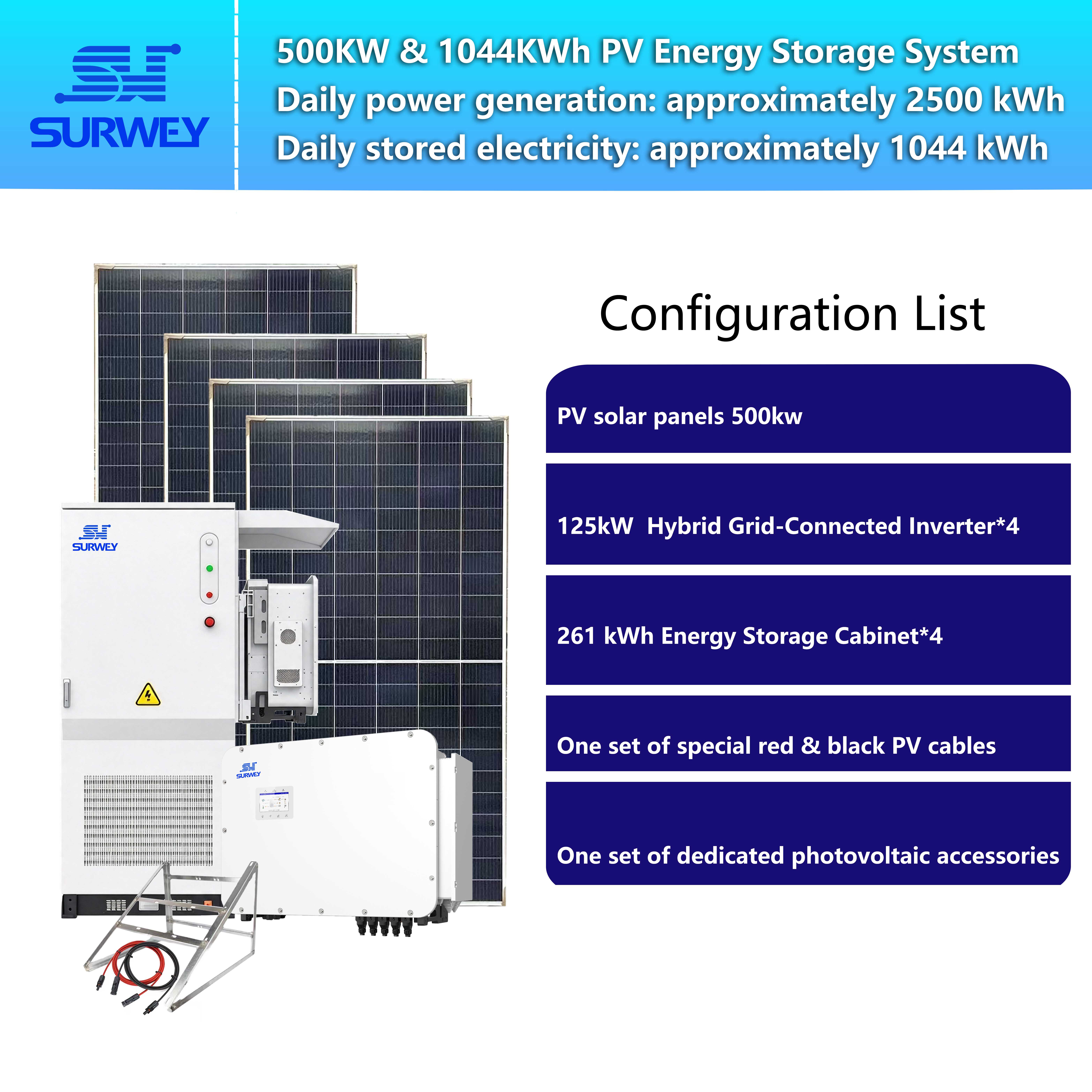 System Configuration Diagram
Many practitioners focus only on installed capacity while overlooking underlying logic. After PV modules produce DC power, what role does the inverter play? When does the energy storage system charge and discharge? How does power flow inside the system during daytime, evening and blackouts? Avoiding obscure industry clauses, this article breaks down the practical deployment logic of overseas commercial and industrial PV-ESS projects from product features, string design and full-cycle operating principles.
I. Core Hardware Breakdown: System Configuration Adapted to West African Site Conditions
Hardware compatibility with tropical harsh environments is the primary prerequisite for reliable PV-ESS operation. The project comprises three major units: PV arrays, 125kW hybrid grid inverters and 125kW/261kWh liquid-cooled outdoor energy storage cabinets. Equipment parameters are tailored for high temperatures, strong ultraviolet radiation and unstable grids in Côte d’Ivoire.
1. 125kW Hybrid Grid Inverter

Many regard inverters simply as DC-to-AC converters. In hybrid grid systems, however, this 125kW inverter acts as the core scheduler of the whole system. Four units are deployed in parallel, each rated at 125kW. The four work in coordination to match the 500kWp PV array.
It features practical characteristics well suited to West African factory sites:
- Equipped with multiple independent MPPT channels to connect multiple PV strings. Where rooftops suffer partial shading or arrays face inconsistent orientations, shaded circuits can be separated independently, preventing output degradation of the entire system caused by affected modules. It is compatible with high-power PV modules to maximize PV generation potential.
- Supports seamless switching between grid-tied and off-grid modes with ultra-short transition time. When the local grid fails unexpectedly, the device quickly switches to island backup mode to keep critical production equipment running and avoid production interruption. Once grid power is restored, the system automatically reverts to grid-tied mode without on-site manual intervention.
- Supports parallel expansion of multiple units. In this project, four inverters operate collaboratively with automatic power balancing. Additional inverters can be added to scale up the system if the factory expands production capacity later.
- Allows reasonable PV oversizing. PV modules suffer power derating under tropical high temperatures. Moderate oversizing helps capture weak irradiance in early morning and late afternoon to boost overall equipment utilization.
- Embeds fundamental energy management logic, supporting multiple operation strategies including self-consumption, peak shaving and backup protection. It sends charge and discharge commands to energy storage cabinets without excessive external accessories. Built-in communication ports enable remote operation monitoring, which is highly valuable for overseas projects with limited on-site O&M manpower.
Hardware limits must be clarified: the inverter MPPT voltage window ranges from 250V to 850V, and the maximum allowable open-circuit voltage on the module side is 1000V. All subsequent PV string calculations must stay within these parameters. Even premium PV modules cannot deliver full performance if string design violates hardware constraints.
2. 125kW/261kWh Liquid-Cooled Outdoor Energy Storage Cabinet
Four integrated liquid-cooled energy storage cabinets are deployed, each rated at 125kW/261kWh, adopting lithium iron phosphate cells with IP54 protection rating. Cabinets can be placed outdoors directly without dedicated indoor machine rooms, cutting civil engineering workload and enabling rapid installation and commissioning at overseas plant sites.
Midday surface temperature in Côte d’Ivoire often reaches 55–60°C. Conventional air-cooled energy storage systems face heavy heat dissipation pressure under high ambient temperature. Large temperature differences among cells accelerate battery degradation. This liquid-cooled cabinet uses ethylene glycol aqueous solution for circulating heat dissipation, keeping cell temperature differences within 3°C. Batteries operate within a favorable working range under intense midday sunlight or nighttime cooling, preserving cycle life. The system achieves 8000 cycles at 90% depth of discharge.
Each cabinet integrates battery clusters, aerosol fire suppression devices, temperature and smoke detectors, and a battery management unit. Most wiring and commissioning work is completed at the factory. On-site installation only requires hoisting and cable connection, greatly shortening construction cycles for overseas sites. The DC operating range of energy storage is 728–936V, well matched to the DC side of hybrid grid inverters. Surplus PV power during daytime is stored and released to supply factory loads in evening peak hours or during power outages. Each storage cabinet corresponds to one 125kW inverter in power rating to avoid resource waste from power mismatch.
3. PV Arrays, Mounting Brackets and Cable Accessories

261 kWh Liquid-Cooled Outdoor Energy Storage Cabinet
The PV array adopts 720Wp N-type TOPCon bifacial double-glass high-power modules. Rooftop mounting uses concrete ballast piers without damaging roof waterproof layers. Brackets use U-section steel paired with aluminum alloy guide rails, and fasteners are reinforced against corrosion to resist intense UV radiation and humid rainy local climate, lowering risks of rust and loosening. DC cables are special PV-grade ageing-resistant cables suitable for long-term outdoor exposure. Complete earthing and lightning protection systems are equipped to cope with frequent tropical thunderstorms and secure rooftop equipment.
II. PV String Configuration: Optimizing Power Generation While Complying with Hardware Parameters
After confirming hardware specifications, PV array string design follows. Stringing is not merely series connection of modules. Core design principles: uniform module quantity for all strings of the project; open-circuit voltage not exceeding equipment upper limit under low temperature; operating voltage falling within the inverter’s optimal MPPT range under high-temperature conditions; balanced load distribution across MPPT circuits; compatibility with later on-site maintenance overseas.
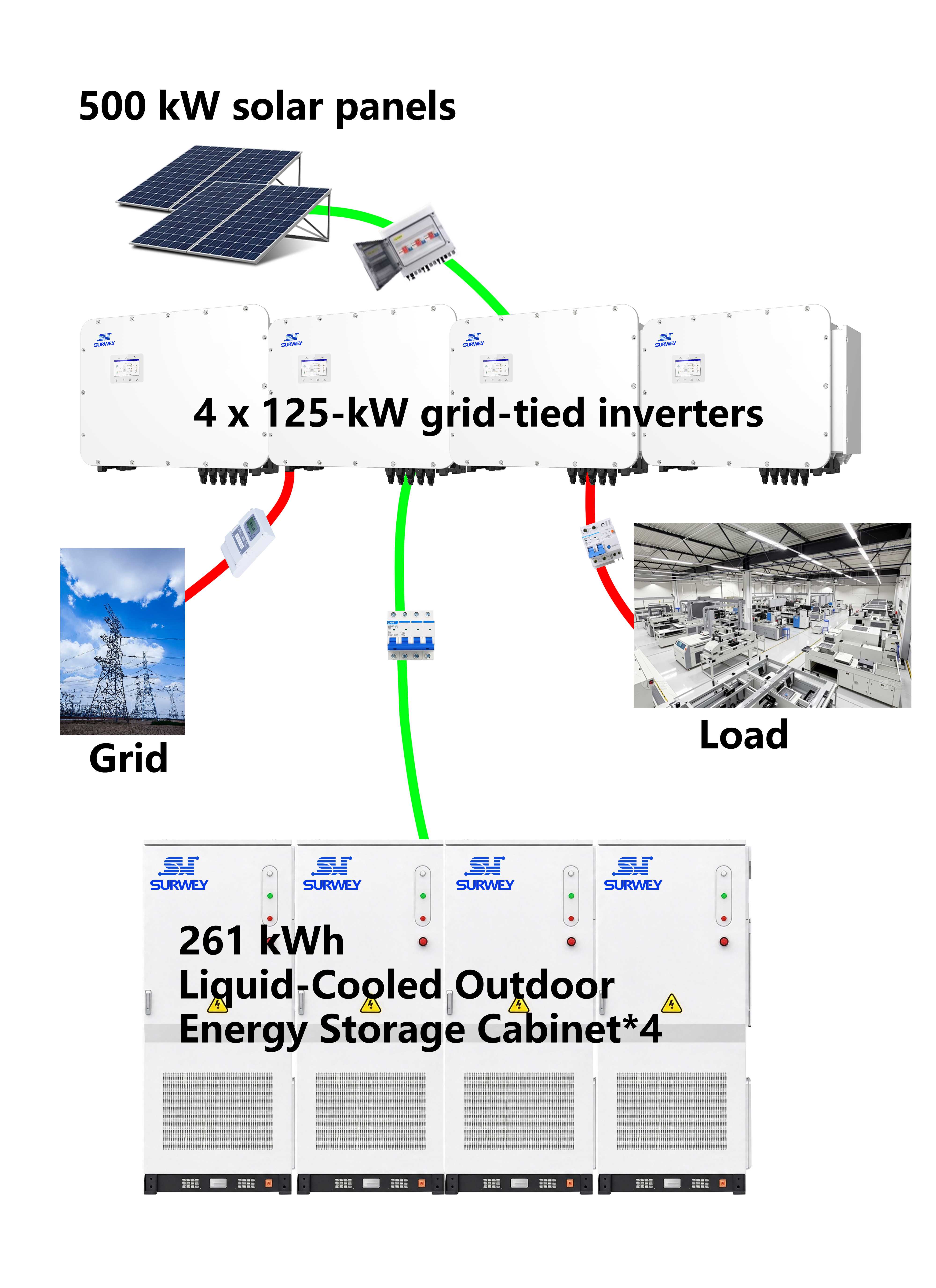 System Topology Diagram
Total installed PV capacity: 500kWp, four parallel hybrid grid inverters. Maximum module-side open-circuit voltage of inverters: 1000V; MPPT operating window: 250–850V. Selected 720Wp N-type TOPCon bifacial double-glass high-power modules. STC parameters: Vmp≈41.9V, Voc≈49.4V; Voc temperature coefficient: −0.34%/°C. Côte d’Ivoire is tropical, yet ambient temperature can drop to 12°C in early mornings of dry seasons. Low temperature raises module open-circuit voltage, which constitutes the critical working condition for string verification. A 16-module series configuration is fully verified as below:
- 16 modules in series: Vmp = 16 × 41.9 = 670.4V, falling within the 250–850V MPPT window ✔
- Low-temperature corrected Voc = 16 × 49.4 × [1 − 0.0034 × (12 − 25)] ≈ 929V < 1000V ✔, retaining sufficient safety margin against equipment voltage upper limit to prevent overvoltage shutdown in cold early mornings.
Power per string: 16 × 720W = 11.52kWp. 44 strings are deployed in practice, bringing total PV power to 44 × 11.52kWp = 506.88kWp. All strings uniformly adopt 16 modules without mixing strings of different lengths.
44 strings are allocated to four 125kW inverters, with 11 strings connected per unit. Each inverter receives 11 strings: 11 × 11.52kWp = 126.72kWp, representing reasonable moderate oversizing. PV modules suffer power derating under tropical midday heat, so sustained peak output at theoretical values is rarely achieved. Moderate oversizing taps generation potential under weak light in morning and evening.
Each inverter is fitted with multiple independent MPPT channels. Strings are evenly distributed across channels, with 2–3 strings connected in parallel per MPPT channel. A single MPPT channel only accepts identical strings with consistent module quantity and array orientation. Mixing strings of different lengths is forbidden to avoid reverse current caused by inconsistent voltage and unnecessary generation loss.
For temporary partial shading induced by rooftop ventilation ducts and parapets, physical zoning is adopted in layout. Arrays prone to shadowing are grouped into separate MPPT channels. Even if short shading occurs in the morning, only the output of this channel is affected instead of the whole inverter, confining shading losses to a small scope.
Construction personnel overseas often have uneven technical proficiency. Uniform string specifications for the whole project reduce wiring errors. During later troubleshooting, maintenance staff do not need to memorize multiple string parameters, lowering on-site inspection difficulty.
III. System Operating Principles: Four Operating Modes from Sunrise to Late Night
System Operating Principle Video
After hardware installation and string construction, PV modules, hybrid grid inverters and liquid-cooled energy storage cabinets interact via internal communication to automatically switch operating modes. The whole system has three energy links:
- DC link: PV modules deliver DC power to inverter MPPT ports; the DC side of energy storage cabinets interconnects with the inverter DC bus.
- AC link: Inverters convert DC power into power-frequency AC power, supplying factory loads on one side and connecting to the public grid on the other.
- Communication control link: Inverters continuously monitor grid status, PV output, state of charge of energy storage and factory load, and automatically issue commands for charge, discharge and mode switching.
A key architectural feature: PV and energy storage share a common DC bus. DC power generated by PV can be directly inverted to supply factory loads, without mandatory prior battery charging and discharging, cutting power loss from one extra charge-discharge cycle.
Based on the actual factory scenario in Côte d’Ivoire, four operating modes are defined: grid-tied daytime, grid-tied evening/nighttime, peak shaving and island backup during grid outages.
Mode 1: Grid-tied, sufficient sunlight, normal grid
As the sun rises, PV arrays gradually output DC power. Inverter MPPT modules dynamically adjust operating points to capture maximum power under current conditions. Power flow follows fixed priority: PV power supplies factory workshop production loads first. If PV generation exceeds factory consumption, surplus power charges the energy storage cabinets. Once energy storage reaches the upper set limit, the system restrains PV output and stops charging.
Example scenario: Midday PV output 420kW, factory workshop consumption 260kW. 260kW directly feeds production lines, and the remaining 160kW surplus charges the energy storage system. When batteries are fully charged, the inverter adjusts MPPT operating points to reduce PV output. Thanks to rigorous string design in advance, PV output voltage remains stable, inverters maintain steady tracking, and energy storage charging power avoids frequent violent fluctuations, guaranteeing charging efficiency.
Mode 2: Grid-tied, evening or cloudy days, insufficient PV output, normal grid
When solar irradiance weakens, PV generation fails to meet factory power demand. All PV output prioritizes load supply. Energy storage discharge fills the power gap. When battery state of charge drops to the preset lower protection limit, energy storage stops discharging, and the remaining power deficit is covered by utility grid power.
The factory peak shaving logic follows this workflow. Even with partial PV output, energy storage increases discharge when factory loads spike to reduce power drawn from the grid and ease peak power pressure.
Mode 3: Grid-tied nighttime, no PV output, normal grid
After sunset, PV arrays cease power generation and no DC input exists on the DC bus. The system runs according to preset strategies: grid power can charge energy storage if required. Energy storage discharges to meet factory demand, and utility power supplements shortages. A battery lower SOC limit is configured to prevent deep discharge and cell degradation.
Mode 4: Island backup mode, sudden grid outage
Inverters continuously monitor grid voltage and frequency. Once grid faults are detected, the system rapidly disconnects from the public grid to prevent backfeeding to the faulty external grid. Meanwhile it switches operating mode to establish stable voltage and frequency autonomously. PV and energy storage form a microgrid to guarantee power supply for critical factory equipment.
Under island conditions, PV supplies production loads first when sunlight is available, and surplus power charges batteries. Under low irradiance, energy storage discharge supports loads. If total factory load exceeds the maximum supply capacity of PV plus energy storage, the system automatically sheds non-critical loads to prioritize core equipment and prevent overall overload shutdown.
After external grid faults are repaired, inverters verify stable grid parameters, complete voltage and frequency synchronization, close breakers and smoothly switch back to grid-tied mode, with no manual on-site operation required.
Conventional grid-tied PV inverters shut down immediately during blackouts and have no backup power capability. The core value of this hybrid grid system lies here, which is why the factory selected PV-ESS rather than standalone PV.
IV. High-performance PV-ESS Projects: Integrated Hardware, String Design and Operation Strategy
Many project stakeholders assume that adopting well-known brand equipment guarantees success. Yet with identical PV modules, inverters and energy storage cabinets, different string schemes and operation strategies lead to obvious gaps in power generation and supply stability.
West African markets like Côte d’Ivoire enjoy abundant solar resources, yet high temperatures, temperature swings, grid instability and tough site construction conditions pose objective challenges. Project design cannot simply copy reference parameters. It must adapt to local climate, building conditions and hardware boundaries, and plan power flow logic for various scenarios, converting theoretical parameters into usable power for factories.
An increasing number of Chinese PV and energy storage products are deployed across Africa. What is exported is not merely hardware equipment, but a full energy solution adapted to local environments. No project succeeds effortlessly. Every voltage verification and every energy logic setting lays the foundation for long-term stable system operation.


