
In-depth Analysis: System Logic and Trade-off Scenarios for PV Combiner Boxes, Battery Combiner Cabinets and Inverters
Foreword
“Within an integrated photovoltaic-storage system, the vast majority of engineers are familiar only with the application of PV-side combiner boxes, yet they are highly prone to confusing the two independent systems of PV DC combiner boxes and battery DC combiner boxes. Two typical issues are prevalent across many projects: firstly, the indiscriminate installation of PV combiner boxes in small-scale systems, resulting in equipment redundancy, wasted costs, increased voltage drops and a greater number of potential failure points; secondly, the failure to install combiner cabinets where required on the battery side, or the haphazard installation where they are not needed, leading to battery cluster backflow, abnormal voltage equalisation, frequent tripping, BMS protection errors and even fire hazards. Busbar equipment (PV busbar boxes, battery busbar cabinets) has never been standard system equipment, but rather optional equipment selected to suit specific operating conditions. Whether to install busbar devices depends entirely on: the number of strings, the maximum MPPT connection capacity, the roof layout, the number of battery clusters in parallel, the inverter port specifications, and O&M standards and safety regulations.”
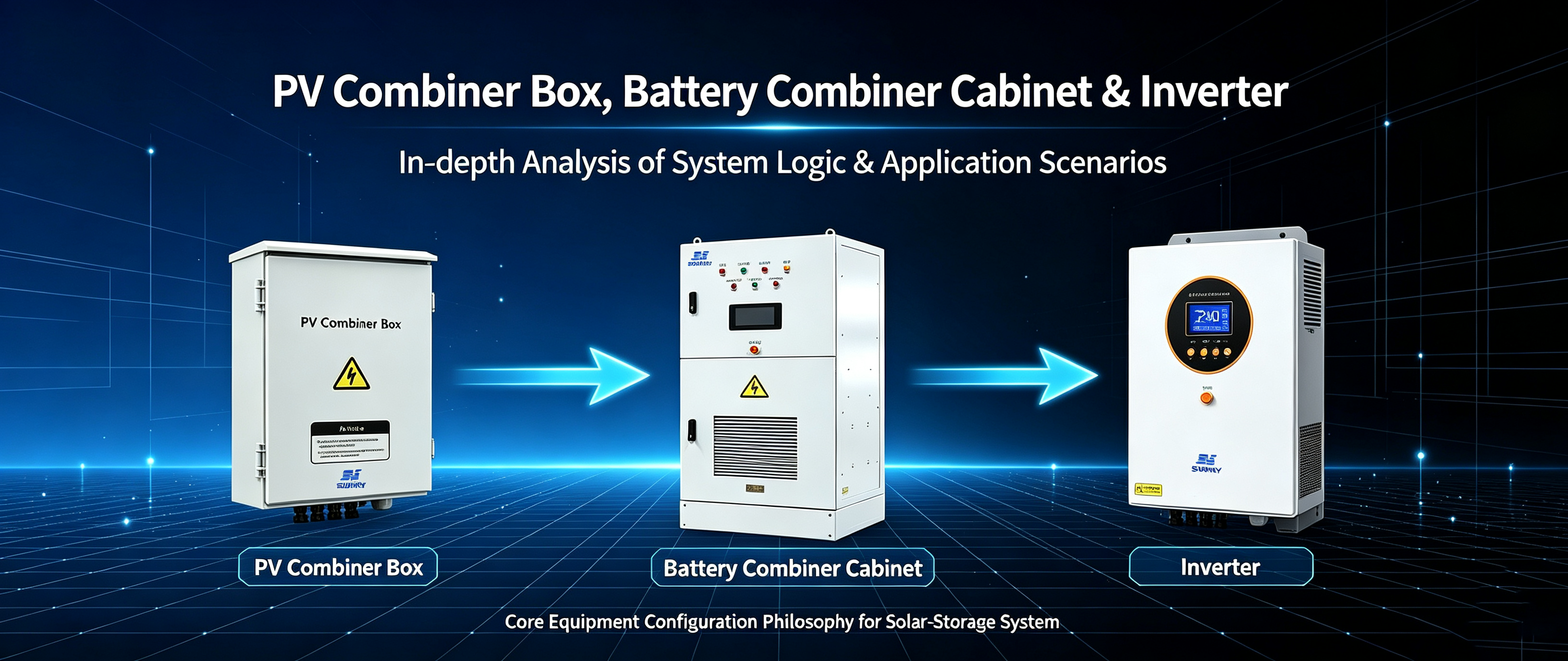
This article provides a comprehensive, systematic and engineering-based analysis of the logic behind PV-side and battery-side busbars, clearly distinguishing the functional differences, suitable applications and scenarios where their use is prohibited for both types of busbar equipment. It thoroughly explains the fundamental industry principles regarding ‘when installation is mandatory, when it can be omitted, and when it must never be installed indiscriminately’, and is applicable to residential, small-scale commercial and industrial, and large-scale commercial and industrial grid-connected / off-grid scenarios, and can serve directly as a standard document for solution design, quotation decisions, technical briefings and project enquiries.
I. Basic positioning of the three core pieces of equipment (dual-system approach combining the photovoltaic and energy storage sides)
1. Photovoltaic combiner box (for photovoltaic use only)
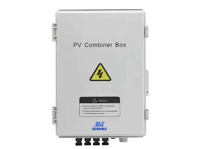
A photovoltaic combiner box is a power distribution and protection device for the DC input side of a photovoltaic system; it serves only the photovoltaic module array and is not part of the battery energy storage circuit.
Key functions: consolidation of multiple photovoltaic strings, independent fuse protection for each string, centralised lightning protection, reduction in the number of cables entering the building, and zoned management of the rooftop array. Key features: it accepts only photovoltaic DC power, not battery DC power, and is physically and logically isolated from the battery system.
2. Battery combiner cabinet (for energy storage applications)
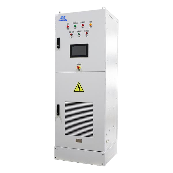
A battery combiner cabinet, also known as an energy storage combiner box or battery parallel cabinet, is a current-combining and protection device for the DC output terminals of batteries, serving only battery clusters.
Core functions: parallel connection and consolidation of multiple battery clusters; independent disconnection and current limiting for each cluster; reverse current protection; equalisation and current distribution; and overall circuit protection. It resolves issues such as circulating currents, voltage differentials and uneven charging and discharging that arise when multiple battery clusters are connected in parallel. Key features: it manages only battery DC and does not connect to PV DC; it is a completely separate piece of equipment from a PV combiner box, and the two must not be used interchangeably or as substitutes for one another.
3. Hybrid inverter (the system’s central hub)
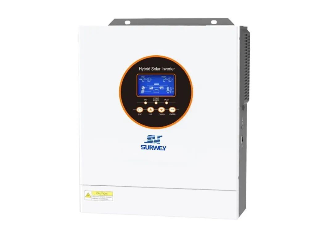
The hybrid inverter serves as the sole energy exchange centre in a photovoltaic-storage system. It comprises a PV (photovoltaic) DC port and a BAT (battery) DC port; these two ports operate independently, with their internal logic functioning without interfering with one another.
PV port: Receives photovoltaic energy and is responsible for PV power input, MPPT tracking and step-up inversion.
BAT port: Responsible for battery charging, battery discharging and bidirectional rectification and inversion.
The inverter’s own PV terminals and BAT terminals are subject to strict limits on the maximum number of connections, the maximum number of parallel clusters and the maximum short-circuit current; these are the core criteria for all combiner box design decisions.
II. Complete System Current Flow (The clearest engineering version across the entire network)
1. Photovoltaic power generation circuit (without energy storage)
PV module strings → Optional PV combiner box → Inverter PV port → Inverter AC power supplied to the load
2. Photovoltaic charging and energy storage circuit
PV modules → Optional PV combiner box → Inverter (PV side) → Internal rectifier → Inverter (BAT side) → Battery cabinet / Battery cluster
3. Battery discharge power supply circuit
Battery cluster → Optional battery combiner cabinet → Inverter BAT port → Inverter AC power to load
🎬 Video: Animation showing the complete current flow in a photovoltaic energy storage system
4. Key Core Principles
Photovoltaic combiner boxes are intended solely for photovoltaic systems, whilst battery combiner cabinets are intended solely for batteries; the two DC circuits are completely separate and must never be connected together. Ninety per cent of minor faults in projects stem from: photovoltaic cables being routed into battery combiner cabinets, battery cables being routed into photovoltaic combiner boxes, or the two combiner systems being used interchangeably.
III. PV Side: Must a combiner box be installed? / Is it optional? Complete criteria for determination
(1) Situations where a photovoltaic combiner box must be installed
1. The number of PV strings exceeds the maximum connection limit of the inverter’s native PV ports
All grid-connected and energy storage inverters have a fixed number of MPPT channels and a maximum number of strings that can be connected in parallel per channel. The standard configuration for mainstream models is: 4 MPPT channels, with a maximum of 2 strings per channel, and a maximum of 8 strings of PV panels connected directly to the inverter.
Should the number of PV strings in a project exceed 8—for example, 10, 12 or 16 strings—it is strictly prohibited to connect them directly in parallel to the inverter terminals. Exceeding the limit for direct connection will result in: terminal overload, uneven current distribution, circuit backflow, hot-spot effects, localised overheating and fire, abnormal MPPT sampling, and a significant drop in power generation.
In such cases, it is essential to use a PV combiner box for upstream consolidation, aggregating multiple strings into multiple main DC bus lines to match the inverter’s MPPT upper limit for connection.
2. The photovoltaic arrays are scattered across multiple rooftops, multiple areas and over long distances
For multi-span factory roofs, rooftops of multiple buildings, mountainous photovoltaic installations and distributed multi-array systems, it is still recommended to install a combiner box even if there are only 6–8 strings in total.
Reasons:
Direct wiring across multiple roofs results in dozens of DC cables entering the building, leading to chaotic cabling in the equipment room.
It is impossible to distinguish which roof each circuit corresponds to, making fault diagnosis extremely difficult.
Long, dispersed cabling creates numerous points of lightning induction, resulting in a high risk of surges.
By collecting power from the roofs at the nearest points, the following can be achieved: zoned management, a reduction in the number of cables entering the building, precise fault localisation, and standardised operation and maintenance.
3. The project requires independent fault isolation for each string (an essential requirement for the commercial and industrial sector)
The ‘inverter direct connection, two-parallel’ configuration has a critical flaw: with two strings connected in parallel to the same MPPT controller, a fault in any one string causes the entire MPPT circuit to shut down, forcing even the undamaged modules to cease generation and resulting in a significant loss of power output.
With the installation of a PV combiner box: each string is protected by an independent fuse; if one string fails, only that string is shut down whilst the others continue to generate power normally. This is a mandatory requirement for commercial and industrial projects and for high-standard O&M by the client.
4. Large-scale outdoor open-air arrays, long stretches of exposed cabling, and projects in lightning-prone areas
Inverters are typically housed in indoor equipment rooms, whilst the photovoltaic arrays are entirely exposed to the elements; DC cables are laid overhead over long distances, resulting in an extremely high probability of induced lightning strikes.
The combiner boxes are equipped with first-level lightning protection at the array end, enabling surges to be discharged directly at the source on the roof. This prevents high-voltage lightning currents from travelling along the cables into the inverter and causing the IGBTs, mainboard and sampling board to fail, thereby significantly reducing the overall unit return rate.
5. Large-scale industrial and commercial projects, standardised acceptance inspections, and projects filed with the State Grid
For large and medium-sized solar-plus-storage projects of 1 kilowatt or more, industry standards stipulate that photovoltaic combiner boxes must be installed as standard to meet the requirements for infrared temperature measurement, string monitoring, data upload, O&M inspections, project acceptance and safety registration.
(2) Situations where the PV combiner box can be omitted entirely (the most cost-effective solution)
If all of the following conditions are met, strings may be connected directly to the inverter with no combiner boxes and zero redundancy:
Total number of PV strings ≤ maximum number of strings that can be directly connected to the inverter (mainstream models ≤ 8 strings)
All modules are concentrated on a single roof or in a single area, with no cross-zone installations or dispersed arrays
The number of MPPT channels in parallel per circuit is strictly ≤ the upper limit specified in the manufacturer’s manual (generally a maximum of 2)
Module model, power rating, number of modules in series, orientation and tilt angle are completely identical
Cable lengths are short, cabling is centralised and there is sufficient space in the equipment room
Advantages: Reduces the number of two-level terminal blocks, minimises DC voltage drop, reduces contact resistance, lowers the probability of faults, and saves on equipment, installation and ancillary material costs; it is the standard practice offering the best value for money in small-scale energy storage projects.
(3) Strict prohibitions regarding provincial distribution boxes (which must under no circumstances be breached during construction)
It is strictly prohibited to forcibly connect modules in parallel or series beyond the maximum number permitted by the MPPT controller.
It is strictly prohibited to mix new and old modules, or modules of different power ratings or with different numbers of strings, in parallel or series.
It is strictly prohibited to run cables haphazardly over long distances or to carry out installations with exposed wiring without lightning protection.
It is strictly prohibited to connect dispersed arrays across multiple roofs directly without a central collection point.
IV. Key New Addition: The complete logic for selecting or omitting battery-side busbar cabinets (battery busbar boxes)
This is a crucial point that is missing from the vast majority of technical documentation: whilst photovoltaic systems can operate without a combiner box, the logic behind battery-side combiner cabinets is entirely different, and the risks associated with connecting multiple battery clusters in parallel are far greater than those associated with connecting photovoltaic modules in parallel.
(1) The key role of the battery busbar cabinet
Parallel balancing and current sharing for multi-cluster batteries to suppress inter-cluster circulating currents
Independent circuit breakers/fuses for each cluster; individual cluster disconnection in the event of a fault
Protection against overcurrent, short circuits, reverse connection and reverse discharge in the main circuit
Unified voltage sampling, balanced charging and discharging, and protection to ensure BMS stability
Resolves issues such as frequent tripping, imbalance, incomplete charging and incomplete discharging caused by voltage differences in multi-cluster parallel configurations
(2) Scenarios where a busbar cabinet must be installed on the battery sid
1. Number of battery clusters: ≥2 clusters connected in parallel (mainstream commercial and industrial operating conditions)
Whenever a project involves expanding capacity by connecting two or more battery clusters in parallel, a battery combiner cabinet must be installed.
Risks of direct connection without a combiner cabinet:
Minor voltage differences between clusters can generate internal circulating currents
During charging, some clusters may become overcharged whilst others remain undercharged
During discharge, some clusters may become severely depleted whilst others remain idle
The BMS frequently reports voltage difference faults, implements current limiting, or shuts down the system
Long-term circulating currents lead to premature cell degradation, swelling and the risk of thermal runaway.
A busbar cabinet enables independent current limiting, isolation and equalisation for each cluster; it is an essential safety device for multi-cluster parallel configurations and must not be omitted under any circumstances.
2. High-capacity energy storage systems, high-voltage stacked battery systems
High-voltage battery cabinets contain a large number of battery strings and have a high total energy capacity; should a short circuit occur in a single string, the instantaneous current would be extremely high. Battery combiner cabinets are equipped with total-level short-circuit protection and reverse current protection, and form the safety baseline for high-voltage energy storage systems.
3. Off-grid energy storage, uninterruptible power supply and load-sensitive projects
In off-grid conditions, where batteries are subjected to frequent high-current charging and discharging and frequent load spikes, a configuration comprising multiple clusters connected in parallel without a combiner box is highly prone to protection trips, power cuts, restarts and system instability; it is therefore essential that the combiner box maintains stable voltage and current.
4. Party A has specific acceptance criteria and safety standards for energy storage systems
The acceptance criteria for energy storage systems are significantly stricter than those for photovoltaic systems; parallel connections of multiple clusters must be equipped with branch protection devices, and a combiner cabinet is a standard requirement for acceptance.
(3) Scenarios on the battery side where a busbar cabinet is not required (the only permitted operating condition)
For systems comprising only single-cluster batteries or single-cabinet battery units, the battery combiner cabinet can be omitted entirely.
Principle: Single-cluster batteries do not involve parallel circulating currents or voltage differences between multiple clusters, and do not require current shunting or balancing. The battery cabinet comes equipped with a factory-fitted high-voltage main switch and a full suite of BMS protection features; a single positive and negative cable connects directly to the inverter’s BAT ports, making this the most compliant, safe and optimal connection method.
Suitable applications:
All residential single-cabinet energy storage systems
Small-scale commercial and industrial single-unit, single-cluster battery systems
Projects with low battery capacity and no requirement for parallel expansion
(4) The Golden Rules of Battery-Side Engineering
Single battery string → No battery combiner box required (cost-saving and compliant)
Two or more strings connected in parallel → Battery combiner box mandatory (mandatory safety requirement)
Photovoltaic combiner boxes are for photovoltaic systems; battery combiner boxes are for batteries; they are never interchangeable
V. Essential Knowledge for Engineers: PV Combiner Boxes vs. Battery Combiner Cabinets – A Comparison Table of Key Differences
| Comparison Item | PV Combiner Box | Battery Combiner Cabinet |
|---|---|---|
| Application Object | Serves the PV module array | Serves the battery cluster energy-storage array |
| Condition for Omission | Can be omitted when string count is small & rooftop is concentrated | Only omittable for a single cluster; never omittable for multiple clusters |
| Risk Level (Consequence of Omission) | Omitting the combiner box: at most reduced power output & harder fault diagnosis | Omitting the combiner cabinet: directly risks cell thermal runaway, fire, and circulation-induced battery scrap |
| Protection Logic | Overcurrent protection, lightning protection, single-string fault protection | Anti-circulation, anti-voltage-difference, anti-reverse charge/discharge, anti-inter-cluster mutual charging |
| Cost Trade-off Logic | Small PV systems can save cost by omitting the combiner box | For multi-cluster battery systems, the combiner cabinet must never be omitted for safety |
VI. A mnemonic for quick judgement applicable across all scenarios
Mnemonic for photovoltaics:
If there are few strings, the roof area is concentrated and the number of ports is sufficient, a combiner box is not required; if there are many strings, the roof area is dispersed and the number of ports exceeds the limit, a combiner box must be installed; whilst equipment can be omitted in small systems, operation, maintenance and safety must not be compromised in large systems.
Mnemonic for batteries:
Connect a single string directly to a single cabinet; there is no need to connect it to a battery combiner cabinet. When two strings are connected in parallel, they must be combined, and safety protection must not be omitted. For photovoltaic battery distribution boxes with two circuits, mixing circuits or connecting them incorrectly is strictly prohibited.
VII. Practical Project Experience: Case Studies of Comprehensive Implementation Scenarios
Case Study 1: Small-scale domestic solar-plus-storage system
Configuration: Standard-power inverter, 6 strings of PV modules, centralised installation on a single-pitch roof, single-cabinet battery system
Assessment: The number of PV strings does not exceed the limit; centralised installation on the roof → no PV combiner box required; the battery system consists of a single cluster and a single unit → no battery combiner cabinet required
Solution: PV direct-connect inverter and battery direct-connect inverter; the simplest and most optimal solution, with the lowest cost and lowest failure rate.
Case Study 2: Small and medium-sized commercial and industrial premises, 8-string photovoltaic system, dual-roof installation
Configuration: The system can directly connect up to 8 strings of PV modules; in practice, there are exactly 8 strings, but these are spread across two roof areas.
Assessment: The number of strings does not exceed the limit, but the roofs are separate, the cabling is haphazard and O&M is difficult → It is recommended to install a PV combiner box. If the modules are connected in dual-cluster parallel configuration → a battery combiner cabinet must be installed.
Case Study 3: High-power commercial and industrial photovoltaic system with 12 strings of modules installed on a single roof
Determination: Number of strings exceeds the inverter’s direct connection limit → Mandatory installation of a PV combiner box; three cell clusters in parallel → Mandatory installation of a cell combiner cabinet
Case Study 4: Single-cluster batteries, multi-string photovoltaic systems exceeding limits
Conclusion: Photovoltaic system exceeds limits → Install a single-cluster photovoltaic combiner box → No need for a battery combiner cabinet
VIII. A Summary of the Eight Most Common Pitfalls in the Industry
× Myth: Combiner boxes are standard equipment and must be installed in all systems
✔ Fact: Combiner boxes are entirely optional; they can be omitted entirely in small systems
× Myth: Photovoltaic modules can be connected directly, and batteries can also be connected in parallel without restriction
✔ Fact: Connecting multiple battery clusters in parallel poses far greater risks than photovoltaic modules; direct connection without a cabinet is strictly prohibited
× Misconception: PV combiner boxes can replace battery combiner cabinets
✔ Fact: The protection logic, voltage withstand capacity and arc-extinguishing ratings are entirely different; mixing them will cause equipment to explode
× Misconception: Omitting combiner boxes constitutes cutting corners
✔ Fact: Omitting combiner boxes whilst complying with regulations is an optimised solution that reduces potential failure points
× Misconception: Multiple battery clusters can be balanced solely by the BMS
✔ Fact: The BMS can only sample and trigger alarms; it cannot suppress physical circulating currents, so a combiner cabinet is essential for current shunting
× Misconception: When two strings are connected in parallel to the same MPPT, a fault in one string has no impact
✔ Fact: In standard inverter direct-connection mode, a fault in one string causes the entire circuit to shut down
× Misconception: A distributed rooftop PV system with few strings does not require a combiner box
✔ Fact: Prioritising the consolidation of distributed arrays is an essential requirement for operations and maintenance
× Misconception: All battery systems require a combiner cabinet
✔ Fact: This is only necessary for parallel configurations; standalone systems with a single cluster require none at all
IX. Final Standardisation Design Conclusions
PV combiner boxes: Consider the quantity, distribution and number of ports; omit where possible, but install where necessary, with the primary objectives being to optimise costs, optimise cabling and enhance operation and maintenance.
Battery combiner cabinets: Omit for single-cluster systems, but install for multi-cluster systems; do not prioritise cost savings, but instead place safety, voltage stabilisation, prevention of loop currents and equipment lifespan as the top priorities.
These two sets of combiner equipment each fulfil distinct functions; they must never be used interchangeably or connected in a mixed configuration. This is a core specification in the design of photovoltaic-storage systems.
Optimal engineering solution: Avoid unnecessary equipment where possible, whilst ensuring that essential safety equipment is not compromised, thereby achieving reasonable costs, safety compliance, hassle-free operation and maintenance, and long-term stability.


